


| Issue |
EPJ Nuclear Sci. Technol.
Volume 12, 2026
|
|
|---|---|---|
| Article Number | 18 | |
| Number of page(s) | 15 | |
| DOI | https://doi.org/10.1051/epjn/2026004 | |
| Published online | 12 June 2026 | |
https://doi.org/10.1051/epjn/2026004
Regular Article
Loading pattern design of the soluble boron-free SMR using LEU+ fuel and multitype burnable absorbers
KEPCO International Nuclear Graduate School, 658-91 Haemaji-ro, Seosaeng-myeon, Ulju-gun, Ulsan, 45014, Korea
* e-mail: This email address is being protected from spambots. You need JavaScript enabled to view it.
Received:
2
October
2025
Received in final form:
12
December
2025
Accepted:
23
March
2026
Published online: 12 June 2026
Abstract
Small Modular Reactors (SMRs) represent a promising technology for addressing global energy demands. South Korea’s innovative SMR (i-SMR) is targeting soluble boron-free (SBF) operation to simplify reactor systems and eliminate boric acid corrosion. However, the elimination of soluble boron necessitates alternative reactivity control strategies to manage excess reactivity throughout extended fuel cycles, particularly for 30+ month operational periods that require higher initial fuel enrichment levels. This study evaluates the integration of three distinct burnable absorber (BA) approaches to achieve optimal reactivity control in LEU+ fuel configurations for extended cycle operation. The first approach employs Highly Intensive Gadolinia burnable Absorber (HIGA) rods containing concentrated Gd2O3 embedded in an alumina matrix, which achieves strong spatial self-shielding to extend reactivity control duration throughout the cycle. The second approach utilizes erbia (Er2O3) at natural isotopic composition uniformly admixed with fuel, providing smoother reactivity depletion characteristics through resonance-dominated burnup that supports long-cycle operation. The third approach involves enriched gadolinia mixed directly into fuel pins, leveraging high fractions of Gd-155 and Gd-157 isotopes to extend reactivity suppression while utilizing spatial self-shielding effects to slow absorber burnout. The synergistic combination of these three burnable absorber strategies enables effective management of the substantial excess reactivity inherent in LEU+ fuel while achieving cycle lengths exceeding 30 months. Core analysis is performed using the validated PRAGMA/SPHINCS nuclear design code system, where PRAGMA generates pin-level multigroup cross sections and depletion data, while SPHINCS performs three-dimensional pin-by-pin diffusion calculations. This approach to burnable absorber deployment maintains near-critical conditions throughout the extended cycle while avoiding the limitations of conventional single-absorber strategies that deplete too quickly in SBF operation. The successful demonstration of 35+ month fuel cycles through optimized burnable absorber integration significantly enhances SMR economic competitiveness by reducing refueling frequency, minimizing operational downtime, and improving overall plant capacity factors. These results provide a pathway for commercially viable SMR deployment with enhanced economic performance while maintaining the safety and operational flexibility advantages of soluble boron-free reactor designs.
© M. Latoch and J. Yoon, Published by EDP Sciences, 2026
 This is an Open Access article distributed under the terms of the Creative Commons Attribution License (https://creativecommons.org/licenses/by/4.0), which permits unrestricted use, distribution, and reproduction in any medium, provided the original work is properly cited.
1. Introduction
SMRs can be consider as a future flexible energy source for generating electricity. It is a technology that can play a role in meeting increasing global energy demands, stemming largely from population growth and the expanding needs of the developing world, including increased urbanization and industrialization [1]. As one of the world’s nuclear energy leaders, South Korea has pursued SMR technology development for the last twenty years, especially in developing an innovative SMR (i-SMR) [2, 3]. Building on proven PWR technology, the i-SMR targets soluble boron-free operation, extended fuel cycles, enhanced thermal margins, and flexible load-following. Eliminating soluble boron simplifies the Chemical and Volume Control System (CVCS) and avoids boric-acid corrosion, but it also eliminates a primary means of cycle-wide reactivity compensation. By removing boron from the coolant system, excess reactivity must be controlled by alternative means – burnable absorbers and control rods to ensure that the reactor remains safely critical. This control is especially critical in a long-cycle (e.g. 24-month, 36-month) core, where higher initial fuel enrichment is required to achieve the cycle length, but at the same time causing increase of excess reactivity and power-peaking risk [4].
In the absence of soluble boron, reactor must rely on a combination of control rods and burnable absorbers to regulate core reactivity. Control rods can compensate some excess reactivity, but SMR designs typically have a limited number of rods, and over-reliance on them is problematic; deep insertions can erode shutdown margin and distort local power, while aggressive rod motion risks positive reactivity transients (e.g., rod-ejection) [5, 6]. Thus, alternative BA strategies are essential to sustain near-critical conditions throughout the cycle under SBF operation. In conventional large PWRs, IFBA (ZrB2 coatings), WABA (B4C rods), and Gd2O3 admixed in fuel are widely used to offset excess reactivity and help maintain negative Moderator Temperature Coefficient (MTC) while flattening power [5]. For the soluble boron-free i-SMR, however, traditional configurations alone are not adequate for an extended cycle because standard poisons can deplete too quickly, raising mid-cycle reactivity [7]. Recent studies have begun exploring multi-absorber combinations in SBF SMR concepts, including designs with erbia and HIGA-type discrete absorbers [8]. Other work has also examined HIGA combined with IGD, but these studies were limited to dual-absorber approaches [5]. By combining HIGA, IGD and erbia simultaneously within an LEU+ fuel environment, the present work extends these preliminary investigations and demonstrates how a three-absorber hybrid strategy can be used to achieve a well-balanced, long-cycle SBF core.
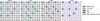 |
Fig. 1. The configurations of the designed FAs without BA and with different BAs. |
Building on these developments, the present work evaluates three distinct burnable absorber approaches for reactivity control in the i-SMR core under SBF conditions. First, HIGA burnable absorber is considered. HIGA refers to discrete absorber rods containing a concentrated Gd2O3 load embedded in an inert alumina matrix. By concentrating gadolinium in separate BA rods rather than homogenously in fuel, the HIGA design achieves very high local absorption and strong spatial self-shielding, which slows the gadolinium depletion rate. This allows HIGA rods to sustain reactivity hold-down over a longer period of the cycle [7, 9]. Second, erbia at natural isotopic composition is uniformly admixed with fuel. Erbia’s slower, resonance-dominated depletion smooths the reactivity swing and supports long-cycle operation [4]. Third BA is integral gadolinia mixed into fuel. Gadolinia is a well-established burnable absorber in light-water reactors, owing to the extraordinary thermal neutron capture cross-sections of Gd-155 and Gd-157. In a boron-free i-SMR core, gadolinia-bearing fuel pins can provide a substantial initial reactivity suppression; however, conventional gadolinia tends to deplete rapidly in the early stage of burnup as the Gd isotopes are transmuted, which can lead to a pronounced reactivity rise mid-cycle. One method to mitigate this behavior include increasing the gadolinia loading or enriching the gadolinium in the key absorber isotopes, as well as leveraging self-shielding by concentrating gadolinia in certain regions of the fuel. For instance, using enriched gadolinia rods with high fractions of Gd-155 and Gd-157, has been shown to extend the duration of reactivity control without compromising the cycle length, by taking advantage of the spatial self-shielding effect to slow the burnout of the absorber [10].
Core analysis is performed using the PRAGMA and SPHINCS computational tools. PRAGMA (Power Reactor Analysis using GPU-Accelerated Monte Carlo Algorithm) is a Monte Carlo code developed for efficient reactor physics calculations on modern computing architectures. In this study, PRAGMA is used to generate pin-level multigroup cross sections and depletion data for the SMR fuel assemblies, capturing the detailed interactions of neutrons with the fuel and absorber materials. A four-group energy structure is adopted for all PRAGMA/SPHINCS calculations. The presence of strong absorbers such as Gd2O3 and Er2O3 did not require altering the group structure. Their spectral effects are accounted for through the SPH-based equivalence correction, which ensures that the few-group cross sections reproduce the reaction rates and neutron leakage of the continuous-energy reference solution [9]. The few-group cross sections produced by PRAGMA are then used in the SPHINCS (Simplified P3 Pin Homogenized Innovative Neutronics Core Simulator) code – a three dimensional nodal diffusion solver enhanced with a pin-by-pin SPH (Superhomogenization) equivalence method– to simulate the full core depletion with high accuracy [11]. This two-step PRAGMA/SPHINCS approach has been demonstrated to achieve excellent agreement with reference whole-core transport calculations, even for cores featuring strong flux heterogeneities from burnable absorbers and complex control rod configurations [9] (see Tab. 1).
2. Core analysis of a soluble boron-free SMR with HIGA, Gd2O3 and Er2O3
2.1. Properties of gadolinia and erbia
Gadolinia and erbia are used as solid burnable absorber additives in uranium dioxide fuel. Introducing Gd2O3 or Er2O3 displaces some UO2 and slightly reduces the heavy metal loading. For example, a 10 wt.% Gd2O3–UO2 fuel contains roughly 0.9% fewer uranium atoms per cm3 than pure UO2. Gadolinia doping is known to reduce the thermal conductivity of the fuel matrix due to lattice defects and impurity scattering. Gd-bearing fuel rods run at somewhat higher temperature gradients [12]. By contrast, erbia in small concentrations has a negligible effect on UO2 thermal conductivity [13, 14]. The reactivity worth of gadolinia and erbia stems from particular isotopes of Gd and Er that have high neutron capture cross sections. Natural gadolinium contains two odd-mass isotopes, Gd-155 and Gd-157, which together make up to 30.5% of Gd and are extraordinary thermal neutron absorbers. At 0.025 eV, Gd-155 has a thermal absorption cross section of about 60 700 barns, and Gd-157 is even higher at roughly 253 000 barns [15]. These values are several orders of magnitude above typical absorbers. By contrast, natural erbium’s only significant absorber is Er-167, which makes around 22.9% of Er, with a thermal capture cross section ∼650 barns. Other Er isotopes, such as Er-166, Er-168, Er-170, have much lower cross sections and play a minor direct role in absorption [16, 17].
Gadolinia’s very large initial absorption enables it to strongly suppress excess reactivity at beginning of cycle, which is essential in long-cycle designs using higher fuel enrichment under soluble boron-free conditions. Because Gd-155 and Gd-157 are consumed rapidly in the first part of the cycle, the poison effect gradually diminishes, releasing reactivity later and thereby flattening the k-effective curve across burnup. This “burn-out” characteristic makes gadolinia highly effective for limiting the reactivity swing and enabling 18–24 month or longer cycles without soluble boron [18, 19]. Erbia, although weaker in absorption strength, depletes much more slowly due to its resonance-dominated cross section. The persistence of Er-167 throughout irradiation provides sustained reactivity suppression even at mid- and late-cycle, preventing large positive reactivity excursions and helping to extend the cycle length [4]. In practice, gadolinia offers strong front-end control while erbia contributes to long-term stabilization, and the complementary depletion behaviors of the two absorbers can be leveraged in SMR cores to achieve extended operational cycles with stable reactivity control [6, 7].
In addition to their neutronic behaviour, the material properties of gadolinia- and erbia-doped fuels introduce practical fabrication constraints that are relevant for industrial deployment. Erbia–UO2 mixtures are known to be manufacturable using conventional dry blending only up to approximately 2.5 wt.% Er2O3, consistent with the stability ranges discussed earlier. Above this level, experimental studies report abnormal grain growth, increased porosity, and phase separation due to differential diffusion between U, Er, and O, which degrades pellet density and mechanical integrity [20]. At higher erbia concentrations, advanced routes such as co-precipitation or high-energy milling become necessary, increasing fabrication complexity. Similar limitations apply to Gd2O3, whose addition strongly inhibits sintering and tends to increase pellet porosity and susceptibility to cracking. Experimental work has shown that higher gadolinia contents demand stricter control of powder homogeneity and sintering schedules, particularly when isotopically enriched Gd2O3 is used [21].
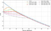 |
Fig. 2. k-inf vs. burnup curves for varying UO2 – Gd2O3 contents. |
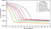 |
Fig. 3. Gd density for IGD assemblies with different gadolinia contents. |
To examine the neutronic characteristics of single absorber analysis, four representative 17×17 fuel assemblies were prepared: a reference assembly without burnable absorbers, an assembly with IGD rods only, an assembly with HIGA rods only, and an assembly composed entirely of erbia-doped fuel rods. The IGD only assembly contains 20 IGD pins with varying Gd2O3 wt.%, the HIGA only assembly includes 20 HIGA pins with different Gd2O3 mol.%, and the erbia only assembly consists of 264 erbia-doped fuel pins with varying Er2O3 wt.%. The cross-sectional configurations of the fuel assemblies are shown in Figure 1.
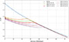 |
Fig. 4. k-inf vs. burnup curves for varying Gd2O3 molar concentrations. |
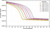 |
Fig. 5. Gd density for HIGA assemblies with different gadolinia concentrations. |
The resulting reactivity curves vs. burnup are compared in Figure 2. For the IGD assemblies with natural and gadolinia concentration, the k-inf curves reflect the fast and relatively uniform burnout of gadolinia mixed directly into the UO2 matrix. At low Gd2O3 contents, the absorber is fully depleted within the first 15–25 MWd/kgU, resulting in a pronounced mid-cycle rise in k-inf. Increasing the weight percent of gadolinia extends the absorber lifetime but still leads to earlier burnout compared to discrete absorber designs. Assemblies containing isotopically enriched gadolinia exhibit stronger initial suppression and slower burnout. The number-density evolution in Figure 3 confirms this behavior: natural isotopic IGD exhibits a very rapid decrease in gadolinia content, while isotopically enriched IGD maintains a slower depletion rate and therefore remains effective for a longer portion of the cycle. However, despite this extended lifetime, the enriched IGD absorbers still deplete slightly faster than HIGA, reflecting weaker spatial self-shielding inherent to integral gadolinia fuel. The HIGA assemblies in Figure 4 show k-inf behavior dominated by strong spatial self-shielding inside the concentrated Gd2O3-Al2O3 pellets. As a result, k-inf initially remains strongly suppressed, followed by a delayed but sharp increase once the absorber burns out. Raising the molar concentration from 8 to 20 mol.% systematically shifts the burnout point to higher burnup, extending the effective suppression window for the highest concentration. The corresponding gadolinia number density evolution in Figure 5 confirms this trend, exhibiting a long self-shielded plateau followed by a rapid depletion phase once the absorber becomes fully exposed. The erbia-doped assemblies shown in Figures 6 and 7 exhibit yet another characteristic behavior distinct from gadolinia based absorbers. As presented in Figure 7, the number density of Er-167 decreases smoothly and monotonically throughout the entire burnup range, without the abrupt depletion phase observed for Gd-155 and Gd-157. This sustained and gradual reduction directly shapes the k-inf evolution in Figure 6, where the curves change slowly over burnup and maintain reactivity suppression well into the mid and late stages of irradiation. Increasing the erbia concentration, further slows the depletion rate, extending the absorber’s effectiveness across the full cycle.
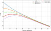 |
Fig. 6. k-inf vs. burnup curves for varying erbia doping concentrations. |
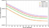 |
Fig. 7. Er density for erbia-doped fuel assemblies with different erbia concentrations. |
2.2. Fuel assembly design and loading pattern for cycle 1
The SMR incorporates a two-batch loading pattern in order to sustain a 36-month operational cycle. In cycle 1, all fuel assemblies are fresh. Eight fuel assembly types were developed, varying in the number of HIGA rods (12–20 rods with Gd2O3 content ranging from 16 mol.% to 20 mol.%) and Integral Gadolinia (IGD) rods with enriched gadolinia (12–16 rods with 8 wt.% Gd2O3). In addition, some assemblies include erbia-doped fuel pins, which are classified into three types: 6.0 wt.% and 6.9 wt.% UO2 with 2.0 wt.% Er2O3, and 6.68 wt.% UO2 with 0.5 wt.% Er2O3. While the standard enrichment of U-235 is set at 6.18% for conventional fuel pins, three assemblies (A02, A04, and A08) consist exclusively of erbia-dopped pins; therefore, their U-235 content is left blank in the table. The layout of these assemblies is shown in Figure 8, and Table 2 summarizes the fuel compositions.
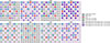 |
Fig. 8. Configurations of FAs for SMR cycle 1. |
Design parameters for FAs for SMR cycle 1.
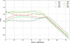 |
Fig. 9. Comparison of k-inf for the first cycle FAs. |
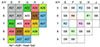 |
Fig. 10. Loading pattern for cycle 1 and control rod pattern in SMR. |
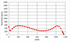 |
Fig. 11. Excess reactivity as a function of burnup for the initial cycle under ARO condition. |
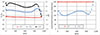 |
Fig. 12. Peaking factors and critical rod position in cycle 1. |
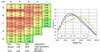 |
Fig. 13. Radial and axial power distributions of the initial cycle (BOC, MOC, and EOC). |
Reactor core calculations were performed using the PRAGMA/SPHINCS codes. PRAGMA is used to generate pin-level multigroup cross sections and depletion data for the i-SMR fuel assemblies, capturing the detailed interactions of neutrons with the fuel and absorber materials. PRAGMA generates homogenized cross sections for each fuel pin, as required by the SPHINCS diffusion solver. Since SPHINCS employs a four-group energy structure, the cross sections produced by PRAGMA are also generated in four energy groups. All neutronic calculations in this work use the ENDF/B-VII.1 nuclear data library. The few-group cross sections produced by PRAGMA are then used in the SPHINCS code – a three-dimensional nodal diffusion solver enhanced with a pin-by-pin SPH (Superhomogenization) equivalence method – to simulate the full core depletion with high accuracy. The i-SMR employs a stainless-steel radial reflector, which is surrounded by the downcomer water region and the reactor vessel wall. In soluble boron-free operation, the responsibility for reactivity control is shifted primarily to control rods, which take over the role that soluble boron normally plays in standard PWRs.
The development of the assembly and core loading pattern followed an iterative neutronic optimization procedure. Initially, a set of candidate fuel assemblies was constructed based on absorber concepts established in recent soluble boron-free studies, particularly those employing enriched gadolinia designs such as HIGA and IGD [5, 7]. Building upon these reference concepts, additional configurations incorporating Er-doped fuel pins were also investigated to test whether adding erbium could provide a further reduction in reactivity swing and contribute to extending the cycle length. Various combinations of burnable absorber content, pin arrangements, and enrichment levels were evaluated using PRAGMA at the lattice level to determine k-inf evolution, spectral behavior, and absorber depletion. Assemblies demonstrating favorable characteristics were selected for subsequent optimization, during which the enrichment was adjusted to achieve the target cycle length while maintaining appropriate safety margins.
For the initial cycle, several loading patterns were examined using 5, 6, and 8 distinct assembly types, together with different shuffling schemes. The configuration with eight assembly types produced the most uniform k-eff behavior and was selected for core-level analysis. For the equilibrium cycle, three to five candidate sets were evaluated in a similar manner, and the configuration employing four assembly types yielded the most favorable performance and was adopted as the reference loading pattern.
For the initial cycle eight fresh fuel assembly types are distributed across the core. The k-inf results corresponding to the burnup for each assembly used in cycle 1 are presented in Figure 9. Assemblies A01–A04 contain high-concentration HIGA rods (20 mol.% Gd2O3), with 16–20 rods per assembly. A01 shows the lowest initial k-inf due to the combination of 20 HIGA rods and 12 IGD rods (8 wt.% Gd2O3, 70% enriched). A03 exhibits a similar trend but with a slightly higher initial k-inf and earlier recovery because it contains only 16 HIGA rods and fewer 2.0 wt.% erbia-doped pins. A02 and A04 share identical absorber configurations–20 HIGA rods and the same erbia distribution–while the higher enrichment in A04 (6.90 wt.% vs. 6.00 wt.%) shifts its entire k-inf curve upward. Assemblies A05 and A07 both include 128 erbia-bearing pins (0.5 wt.% Er2O3) and IGD absorbers (8 wt.% Gd2O3, 50% enriched). Their difference lies in HIGA content: A05 has 16 rods at 16 mol.%, whereas A07 has 12 rods at 18 mol.%. Despite the lower mol.%, A05 contains more total gadolinia, leading to a more sustained suppression, while the smaller HIGA inventory in A07 results in faster burnout and an earlier k-inf rise. Assemblies A06 and A08 share the same HIGA loading (16 rods at 18 mol.% Gd2O3) but differ in secondary absorber strategy. A06 uses 16 IGD rods, producing an early k-inf decrease followed by a HIGA-driven mid-cycle phase and a sharper rise after HIGA burnout. In contrast, A08 replaces IGD with mixed erbia (0.5 wt.% and 2.0 wt.%), giving a characteristic erbia-induced flattening and a more prolonged low k-inf region into late burnup. Assemblies placement was optimized according to the multiplication factor – assemblies with higher reactivity are positioned near the periphery, while those with lower reactivity are placed toward the central region to improve radial power distribution.
Figure 10 presents the initial core loading pattern for Cycle 1, while the right-hand side of the figure illustrates the configuration of the control rod system, consisting of four regulating banks (R1–R4) and one shutdown bank (SB). The i-SMR officially adopts an In-Vessel Control Rod Drive Mechanism [22]. However, a finalized and publicly available reference design specifying the detailed control rod layout within the core has not yet been released. Therefore, the control rod arrangement applied in the present study is adopted from previous conceptual design studies and is consistent with standard SMR mechanical constraints and IV-CRDM integration. All regulating banks use Ag–In–Cd (AIC) absorber material, ensuring stable reactivity control during soluble boron-free operation. The shutdown bank utilizes B4C enriched (95%) in 10B, providing high worth for scram and cold shutdown conditions. The composition of the control rods is identical within each group, with AIC used exclusively in the regulating banks and B4C assigned to the shutdown bank. The control rods are inserted sequentially in the order from R4 to R1, applying a 50% overlap between successive banks. This combined representation emphasizes the relationship between fuel loading strategy and reactivity control, ensuring both cycle length extension and safe reactor operation.
Figure 11 illustrates the excess reactivity for all-rod-out (ARO) condition, expressed in effective full power days (EFPD). The projected cycle length under ARO condition is 1169 EFPD, equivalent to 31 878 MWD/MTU, with a maximum excess reactivity of 554 pcm and an overall reactivity swing of 312 pcm. This result satisfies the design assumption of a 36-month cycle (approximately 1095 days), thereby confirming that the cycle length requirement is achieved. The low values of both reactivity swing and maximum excess reactivity indicate that the selected burnable absorber composition effectively fulfills its purpose, providing strong suppression of excess reactivity.
Figure 12 shows the peaking factors and critical position of control rods with a 50% overlap of the control banks. The Axial Shape Index (ASI) demonstrates a clear downward trend during the early part of the cycle due to the influence of inserted control rods, then stabilizes around mid-cycle, and finally shifts upward near the end of the cycle as the rods are withdrawn. The R3 bank remains fully withdrawn throughout the cycle, indicating that it is not required for routine reactivity compensation. In contrast, R4 exhibits gradual position changes to offset reactivity depletion. At the beginning of the cycle (BOC), R4 is partially inserted and is progressively withdrawn as burnup proceeds, approaching near-full withdrawal toward the end of the cycle. The maximum radial pin peaking factor (Fr) was observed at 1.407 at BOC, while the three-dimensional peaking factor (Fq) reached 2.266 near the end of the cycle. In commercial PWRs, design limits for pin peaking factors are typically 1.45 for Fr and 2.40 for Fq, corresponding to peak linear heat rates of 8.12 kW/ft and 13.61 kW/ft [23]. Owing to the much lower nominal linear power density of 3.86 kW/ft for the i-SMR, the corresponding Fq limit scales to approximately 3.52. Nevertheless, to maintain a conservative margin consistent with standard PWR practice, the present analysis continues to apply the traditional Fq = 2.40 criterion. The right side of Figure 13 presents the axial power distributions at the BOC, middle (MOC), and end of cycle (EOC). At BOC, the axial shape exhibits a pronounced peak in the lower half of the core, reflecting the effect of partially inserted regulating control rods. As the cycle progresses and the rods are gradually withdrawn to compensate for fuel depletion, the power profile flattens and the peak shifts toward the upper region. By EOC, the distribution becomes distinctly top-skewed, illustrating the cumulative impact of reactivity depletion and control rod positioning.
To evaluate the inherent safety characteristics of the SMR design, three key temperature reactivity coefficients were calculated: the Fuel Temperature Coefficient (FTC), the MTC, and the Isothermal Temperature Coefficient (ITC). The FTC reflects the reactivity response to changes in fuel temperature and is governed mainly by U-238 resonance broadening; a negative value ensures immediate stabilization during power excursions.
Reactivity coefficient for Hot Full Power (HFP) at BOC, MOC and EOC of the cycle 1.
Subcriticality (Cold Zero Power [CZP]) at BOC, MOC and EOC of the cycle 1.
The MTC describes the effect of moderator temperature and density changes on reactivity. In conventional borated PWRs it may be weakly positive at beginning of cycle due to soluble boron, but under soluble boron-free conditions it is expected to remain strongly negative owing to spectral hardening and leakage effects. The ITC represents the combined influence of both fuel and moderator temperature changes under uniform heating, providing an overall measure of reactor temperature feedback. In all cases, maintaining sufficiently negative coefficients is essential for stable and safe long-cycle operation, particularly in soluble boron-free cores where burnable absorbers replace soluble boron as the primary reactivity control mechanism.
 |
Fig. 14. Configuration of FAs for equilibrium cycle. |
Design parameters for FAs for equilibrium cycle in SMR.
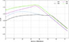 |
Fig. 15. Comparison of k-inf for the equilibrium cycle FAs. |
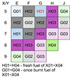 |
Fig. 16. Loading pattern for the equilibrium cycle. |
Reactivity coefficients for the initial cycle are presented in Table 3 and show consistently negative values of FTC, ITC, and MTC across all burnup points. The FTC values are around −2.7 to −3.3 pcm/°C, becoming slightly more negative with burnup. The ITC stays strongly negative, with a values from −63.9 to −70.7 pcm/°C. The MTC is also negative at all stages, ranging from −61.2 to −68.1 pcm/°C. The slightly less negative value MTC at MOC results from the partial depletion of burnable absorbers, which softens the neutron spectrum and reduces the sensitivity of reactivity to moderator density changes. As HIGA and IGD absorbers burn out, the thermal flux fraction increases, weakening the magnitude of the negative coolant-temperature feedback. In addition, fuel depletion and the growing contribution of plutonium isotopes further moderate the MTC around MOC. Toward end of cycle, continued spectral hardening causes the MTC to become more negative again. Table 4 outlines the subcriticality under cold zero power conditions, with the maximum subcritical k-eff for the ARI scenario being 0.90481 at the BOC. This value satisfies the subcriticality criterion of k-eff < 0.95 for ARI conditions. Similarly, the maximum subcritical k-eff under the N-1 condition is 0.95045, which remains below the corresponding N-1 shutdown margin criterion of k-eff < 0.99. These subcriticality calculations confirm that the reactor core maintains adequate shutdown capability under both ARI and N-1 CZP conditions.
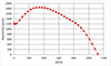 |
Fig. 17. Reactivity versus burnup in the equilibrium core under ARO conditions. |
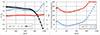 |
Fig. 18. Peaking factors and critical rod position in the equilibrium cycle. |
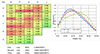 |
Fig. 19. Radial and axial power distributions at BOC, MOC and EOC in the equilibrium cycle. |
2.3. Fuel assembly design and loading pattern for equilibrium cycle
In the equilibrium cycle, the core is composed of four distinct types of fuel assemblies X01 to X04–which differ in their combinations of HIGA rods, enriched IGD rods, and erbia-doped fuel pins. These variations were introduced to balance excess reactivity control, compensate for the reactivity depression caused by once-burned fuel, and maintain a stable power distribution within the two-batch refueling scheme. The geometric configurations of the four assemblies are shown in Figure 14, while Table 5 summarizes their absorber compositions and enrichment levels. The corresponding k-inf behavior for the equilibrium assemblies is presented in Figure 15.
Assemblies X01 and X02 both use 20 mol.% HIGA rods, with 16 rods in X01 and 20 rods in X02. The larger HIGA inventory in X02, together with eight IGD rods (8 wt.% Gd2O3 enriched to 50%), produces the strongest initial reactivity suppression and results in the lowest k-inf among all four assemblies. In contrast, X01 relies only on HIGA and erbia-doped fuel pins (0.5 wt.% and 2.0 wt.% Er2O3), leading to a higher initial k-inf and a smoother reactivity evolution, as shown in Figure 15. Assemblies X03 and X04 contain no HIGA rods and instead employ higher IGD loadings–28 rods in X03 and 24 rods in X04. X03 utilizes 8 wt.% Gd2O3 enriched to 70%, and X04 uses the same IGD concentration with 50% enrichment. Both assemblies include 2.0 wt.% erbia, however, X04 contains erbia-dopped pins with a higher UO2 enrichment because it is placed at the periphery of the core, where greater local reactivity is required to offset radial neutron leakage. Despite their high IGD loading, both X03 and X04 exhibit a much earlier absorber burnout than X01 and X02, whose HIGA content delays the reactivity further into the cycle.
Figure 16 shows the loading pattern for the equilibrium cycle. Fresh fuel assemblies H01–H04 are marked in darker colors, while once-burnt assemblies G01–G04 are indicated in lighter shades of the same color. Figure 17 shown the excess reactivity curve under ARO condition. The calculated reactivity swing is approximately 670 pcm, and the cycle length reaches about 1126 EFPD. The maximum excess reactivity remained below 1850 pcm.
Reactivity coefficients for HFP at BOC, MOC and EOC of the equilibrium core.
Figure 18 shows the evolution of the peaking factors together with the Axial Shape Index and the critical control rod positions during the equilibrium cycle. ASI decreases during the early part of the cycle due to partially inserted regulating rods, stabilizes around mid-cycle, and then shifts upward toward the end of the cycle as the rods are gradually withdrawn. The radial pin peaking factor remained below 1.55 for most of the cycle. The three-dimensional peaking factor reached values up to 2.37 near the end of the simulated irradiation, slightly higher than in the initial cycle. The ASI range was also broader in the equilibrium cycle, reflecting stronger axial shifts induced by the combined effects of once-burned fuel and the regulating banks. The dashed vertical line in Figure 11 corresponds to ∼1100 EFPD, which was the target design cycle length. Up to this point, both Fq and Fr remain within the design acceptance criteria 1.55 for Fr and 2.4 for Fq, respectively. Beyond ∼1100 days, however, Fq shows an increasing trend and begins to exceed the safety limit, indicating that further extension of the cycle would result in peaking factors outside acceptable margins.
Figure 19 illustrates the axial power distribution at BOC, MOC, and EOC. At BOC the profile is bottom-skewed as a result of inserted control rods, becomes little less skewed, and shifts to a distinctly top-skewed shape by EOC due to progressive rod withdrawal and fuel depletion.
Subcriticality (CZP) at BOC, MOC and EOC of the equilibrium cycle.
Table 6 summarizes the reactivity coefficients for the equilibrium cycle at BOC, MOC, and EOC under HFP conditions. All three coefficients remain consistently negative throughout irradiation, confirming strong inherent feedback mechanisms in the boron-free core. The FTC varies only slightly, from −3.3 pcm/°C to −3.2 pcm/°C. The ITC is strongly negative across the cycle, becoming more negative with burnup from −71.0 pcm/°C at BOC to −80.8 pcm/°C at EOC. Similarly, the MTC shows consistently negative values, ranging from −68.3 pcm/°C at BOC to −78.7 pcm/°C at EOC. Compared with the initial cycle, the equilibrium design provides slightly more negative ITC and MTC values. These results confirm that the SBF core maintains appropriately negative temperature reactivity feedbacks over the entire cycle; the strongly negative MTC expected for boron free operation is preserved from BOC to EOC, while the FTC remains stably negative, yielding a consistently negative ITC and supporting safe 36-month operation. Table 7 also verifies the reactor’s subcriticality under ARI and N-1 CZP conditions, with both scenarios meeting their respective shutdown margin criteria. These results further confirm that the reactor maintains sufficient negative reactivity to ensure safe shutdown during operations.
3. Conclusion
This study has developed an advanced core design for the SMR, achieving fully soluble boron-free operation by combining a hybrid burnable absorber strategy–using gadolinia both in HIGA and IGD rods together with erbia, optimally loaded into LEU+ fuel. The results demonstrate that the use of LEU+ fuel can extend the average fuel cycle length up to 36 months.
A soluble boron-free SMR core design was successfully developed and analyzed using the combined PRAGMA/SPHINCS code system. By employing a hybrid burnable absorber strategy–gadolinia in both HIGA and IGD rods together with erbia-doped fuel pins–excess reactivity was effectively suppressed without the use of soluble boron. The PRAGMA Monte Carlo calculations provided accurate pin-level depletion and cross-section data, while SPHINCS simulations confirmed stable core behavior over the full 36-month equilibrium cycle. The reactivity swing was kept below 700 pcm, corresponding to slightly less than 10% of the available regulating and control rod worth, which is approximately 8300 pcm. Peaking factors remained within design limits up to 1100 EFPD, and all safety parameters, including the fuel temperature coefficient, moderator temperature coefficient and isothermal temperature coefficient were consistently negative, ensuring inherent safety margins. These results demonstrate that the proposed SMR configuration achieves the design objective of a three-year boron-free cycle.
Compared with the initial cycle design, the equilibrium configuration achieves the target length with only four distinct fuel assembly types, simplifying fabrication and core management. The combined action of control rods, burnable absorbers, and the strongly negative moderator temperature coefficient provides reliable reactivity control throughout the cycle, confirming the robustness of the soluble boron-free strategy. Moreover, the negative moderator temperature feedback indicates that the design is inherently compatible with temperature-based reactivity control, enabling flexible load-following operation.
Since the present work focuses on the neutronic feasibility of a soluble boron-free LEU+ hybrid absorber concept, detailed manufacturing and QA assessments associated with the larger number of pin types were not included. These practical fabrication constraints, such as fuel manufacturing complexity, quality assurance requirements, and the overall manufacturability of multi-absorber fuel require dedicated industrial evaluation and are identified as important directions for future work.
A direct comparison with conventional single-absorber strategies (e.g., concepts based on only IGD or only HIGA) would provide an additional quantitative perspective on the benefits of the proposed multi-absorber concept. At the current stage, complementary internal studies are being conducted for alternative dual-absorber configurations, including HIGA with Er2O3 [8]. Moreover, the combined IGD with HIGA configuration has already been investigated for conventional LEU fuel [5], while its behavior in the LEU+ enrichment range considered in this work remains to be assessed. A comparison between single absorber and multi-absorber strategies is therefore identified as an interesting and relevant direction for future work.
Funding
This research received no external funding.
Conflicts of interest
The authors declare that they have no conflicts of interest.
Data availability statement
The computational tools used in this work are institutionally licensed and not publicly available due to proprietary restrictions. Consequently, data associated with this article cannot be disclosed due to legal reason.
Author contribution statement
Conceptualization, Mateusz Latoch; Methodology, Mateusz Latoch; Software, Mateusz Latoch; Investigation, Mateusz Latoch; Formal analysis, Mateusz Latoch; Data curation, Mateusz Latoch; Writing – original draft preparation, Mateusz Latoch; Visualization, Mateusz Latoch; Writing – review & editing, Joo-il Yoon; Supervision, Joo-il Yoon; Resources, Joo-il Yoon; Project administration, Joo-il Yoon.
Acknowledgments
This research was supported by the 2025 Research Fund of the KEPCO International Nuclear Graduate School (KINGS), Republic of Korea.
References
- IAEA, “Deployment Indicators for Small Modular Reactors: Methodology, Analysis of Key Factors and Case Studies,“ International Atomic Energy Agency, Vienna, Austria, 2018 [Google Scholar]
- IAEA, “Advances in Small Modular Reactor Technology Developments: A Supplement to IAEA Advanced Reactors Information System (ARIS) 2024 Edition,“ International Atomic Energy Agency, Vienna, Austria, 2024 [Google Scholar]
- H.O. Kang, B.J. Lee, S.G. Lim, Light water SMR development status in Korea, Nucl. Eng. Des. 419, 112966 (2024) [Google Scholar]
- H. Khalefih, LEU+ loaded APR1400 using accident tolerant fuel cladding for 24-month two-batch fuel management scheme, Nucl. Eng. Des. 55, 2578 (2023) [Google Scholar]
- J.S. Kim, T.S. Jung, J. Yoon, Reactor core design with practical gadolinia burnable absorbers for soluble boron-free operation in the innovative SMR, Nucl. Eng. Technol. 56, 3144 (2024) [Google Scholar]
- J.A. Evans, M.D. DeHart, K.D. Weaver, D.D. Keiser, Jr., Burnable Absorbers in Nuclear Reactors – A Review, Idaho National Laboratory, 2022 [Google Scholar]
- J.S. Kim, G. Bae, J. Yoon, Reactor core design with enriched gadolinia burnable absorbers for soluble boron-free operation in the innovative SMR, Nucl. Eng. Des. 428, 113557 (2024) [Google Scholar]
- J. Kim, J. Yoon, Feasibility of LEU+ fuel loading patterns in the i-SMR with HIGA and Erbia burnable absorbers, in Transactions of the Korean Nuclear Society Spring Meeting, Jeju, Korea (2025) [Google Scholar]
- C. Lim, S.J. Kwon, J. Yoon, Performance analysis of a two-step calculation procedure based on Monte Carlo and pin-wise diffusion methods for PWR core design, Nucl. Eng. Des. 433, 113543 (2025) [Google Scholar]
- D. Kim, J.T. Seo, H.J. Shim, Comparison of BANDI-60 core designs using Pyrex BA and CIMBA, Ann. Nucl. Energy 195, 110119 (2024) [Google Scholar]
- C.H. Lim, Development of Pinwise SP3 Based Fast Core Transient Analysis Methodology and the SPHINCS Code, Seoul National University, 2021 [Google Scholar]
- T. Cardinaels, J. Hertog, B. Vos, L.d. Tollenaere, C. Delafoy, M. Verwerft, Dopant solubility and lattice contraction in gadolinia and gadolinia–chromia doped UO2 fuels, J. Nucl. Mater. 424, 289 (2012) [Google Scholar]
- S.H. Alassaf, Use of erbium as a burnable absorber for the VVER reactor core life extension, Nucl. Energy Technol. 6, 275 (2020) [Google Scholar]
- S. Yamanaka, T. Uno, M.K.T. Suda, T. Matsuda, Thermal and mechanical properties of (U,Er)O2, J. Nucl. Mater. 389, 115 (2009) [Google Scholar]
- R. Federico, G. Antonio, M.C. Donato, M. Cristian, Reassessment of gadolinium odd isotopes neutron cross sections: Scientific motivations and sensitivity-uncertainty analysis on LWR fuel assembly criticality calculations, EPJ Nuclear Sci. Technol. 3, 21 (2017) [CrossRef] [EDP Sciences] [Google Scholar]
- National Nuclear Data Center (NNDC), “ENDF/B-VIII.0 Nuclear Data Library,“ Brookhaven National Laboratory, 2018 [Google Scholar]
- Y.D. Lee, Y.O. Lee, Neutron capture cross section for Er-166 and Er-167, in Proceedings of the Korean Nuclear Society Autumn Meeting, Gyeongju, Korea (2006) [Google Scholar]
- M.J. Bolukbasi, S.C. Middleburgh, M. Dahlfors, W.E. Lee, Performance and economic assessment of enriched gadolinia burnable absorbers, Prog. Nucl. Energy 137, 103752 (2021) [Google Scholar]
- A.A. Galahom, Investigation of different burnable absorbers effects on the neutronic characteristics of PWR assembly, Ann. Nucl. Energy 94, 22 (2016) [Google Scholar]
- M. Durazzo, A.M. Saliba-Silva, E.F. Urano de Carvalho, H.G. Riella, Sintering behavior of UO2–Er2O3 mixed fuel, J. Nucl. Mater. 510, 603 (2018) [Google Scholar]
- M. Durazzo, A.M. Saliba-Silva, E.F. Urano de Carvalhos, H.G. Riella, Sintering behavior of UO2–Gd2O3 fuel: Pore formation mechanism, J. Nucl. Mater. 433, 334 (2013) [Google Scholar]
- S.G. Lim, H.S. Nam, D.H. Lee, S.W. Lee, Design characteristics of nuclear steam supply system and passive safety system for innovative small modular reactor (i-SMR), Nucl. Eng. Technol. 57, 103697 (2025) [Google Scholar]
- Korea Electric Power Corporation (KEPCO) and Korea Hydro & Nuclear Power Co., Ltd. (KHNP), APR1400 Design Control Document, Tier 2 – Chapter 4: Reactor, Korea Electric Power Corporation (KEPCO), Daejeon, Republic of Korea, 2018 [Google Scholar]
Cite this article as: Mateusz Latoch, Jooil Yoon. Loading pattern design of the soluble boron-free SMR using LEU+ fuel and multitype burnable absorbers, EPJ Nuclear Sci. Technol. 12, 18 (2026). https://doi.org/10.1051/epjn/2026004
All Tables
Reactivity coefficient for Hot Full Power (HFP) at BOC, MOC and EOC of the cycle 1.
All Figures
|
Fig. 1. The configurations of the designed FAs without BA and with different BAs. |
| In the text | |
|
Fig. 2. k-inf vs. burnup curves for varying UO2 – Gd2O3 contents. |
| In the text | |
|
Fig. 3. Gd density for IGD assemblies with different gadolinia contents. |
| In the text | |
|
Fig. 4. k-inf vs. burnup curves for varying Gd2O3 molar concentrations. |
| In the text | |
|
Fig. 5. Gd density for HIGA assemblies with different gadolinia concentrations. |
| In the text | |
|
Fig. 6. k-inf vs. burnup curves for varying erbia doping concentrations. |
| In the text | |
|
Fig. 7. Er density for erbia-doped fuel assemblies with different erbia concentrations. |
| In the text | |
|
Fig. 8. Configurations of FAs for SMR cycle 1. |
| In the text | |
|
Fig. 9. Comparison of k-inf for the first cycle FAs. |
| In the text | |
|
Fig. 10. Loading pattern for cycle 1 and control rod pattern in SMR. |
| In the text | |
|
Fig. 11. Excess reactivity as a function of burnup for the initial cycle under ARO condition. |
| In the text | |
|
Fig. 12. Peaking factors and critical rod position in cycle 1. |
| In the text | |
|
Fig. 13. Radial and axial power distributions of the initial cycle (BOC, MOC, and EOC). |
| In the text | |
|
Fig. 14. Configuration of FAs for equilibrium cycle. |
| In the text | |
|
Fig. 15. Comparison of k-inf for the equilibrium cycle FAs. |
| In the text | |
|
Fig. 16. Loading pattern for the equilibrium cycle. |
| In the text | |
|
Fig. 17. Reactivity versus burnup in the equilibrium core under ARO conditions. |
| In the text | |
|
Fig. 18. Peaking factors and critical rod position in the equilibrium cycle. |
| In the text | |
|
Fig. 19. Radial and axial power distributions at BOC, MOC and EOC in the equilibrium cycle. |
| In the text | |
Current usage metrics show cumulative count of Article Views (full-text article views including HTML views, PDF and ePub downloads, according to the available data) and Abstracts Views on Vision4Press platform.
Data correspond to usage on the plateform after 2015. The current usage metrics is available 48-96 hours after online publication and is updated daily on week days.
Initial download of the metrics may take a while.