| Issue |
EPJ Nuclear Sci. Technol.
Volume 12, 2026
Euratom Research and Training in 2025: ‘Excellence and Innovation in the Nuclear Sector’ - edited by Roger Garbil, Seif Ben Hadj Hassine, Patrick Blaise, and Christophe Girold
|
|
|---|---|---|
| Article Number | 9 | |
| Number of page(s) | 8 | |
| DOI | https://doi.org/10.1051/epjn/2026001 | |
| Published online | 04 March 2026 | |
https://doi.org/10.1051/epjn/2026001
Regular Article
Robotic system for fragmentation of steam generators (StarGate)
Technical University of Kosice, Letna 9, Kosice 042 00, Slovakia
a e-mail: This email address is being protected from spambots. You need JavaScript enabled to view it.
b e-mail: This email address is being protected from spambots. You need JavaScript enabled to view it.
c e-mail: This email address is being protected from spambots. You need JavaScript enabled to view it.
Received:
29
March
2025
Received in final form:
27
October
2025
Accepted:
2
January
2026
Published online: 4 March 2026
Abstract
The robotic complex “StarGate” was created in response to a request to design and deliver a device for the Nuclear Power Plant (NPP) V1 in Jaslovské Bohunice for the fragmentation of 12 steam generators. To meet the NPP’s requirements, a transdisciplinary team was assembled, consisting of experts in robotics, cybernetics, machining technologies, materials research, and nuclear energy. The synergy of specialists from all these key fields led to a unique solution with parameters and features that are beyond the current state of the art. The main differentiating parameters compared to the state of the art are as follows:
-
Higher production efficiency and work productivity, comparable even to flame cutting (cutting speed of 1.7 mm/s with a wall thickness of 140 mm). The complete fragmentation of a single steam generator (140 tons) took 45 days.
-
A higher level of process automation and intelligent optimization.
-
Minimal radiation exposure for workers.
-
Minimal aerosol generation and reduced spread of contamination to the surrounding environment.
-
Shorter fragmentation time, thereby reducing overall costs (The complete fragmentation of a single steam generator (140 tons) took 45 days). According to today’s data, there are almost 100 steam generators in the world awaiting fragmentation and further processing (IAEA).
© L. Vargovcik et al., Published by EDP Sciences, 2026
 This is an Open Access article distributed under the terms of the Creative Commons Attribution License (https://creativecommons.org/licenses/by/4.0), which permits unrestricted use, distribution, and reproduction in any medium, provided the original work is properly cited.
1. Introduction
The robotic complex “StarGate” was created in response to a request to design and deliver a device for the Nuclear Power Plant (NPP) V1 in Jaslovské Bohunice for the fragmentation of 12 steam generators (SGs).
The main requirements for the new device were:
-
Minimal contamination of the environment (i.e. almost no flame cutting).
-
Minimal exposure of operators.
-
Resistance of devices to RA radiation.
-
High work productivity given the time of 3 months to fragment one complete steam generator (140 tons).
To meet the NPP’s requirements, a transdisciplinary team was assembled, consisting of experts in robotics, cybernetics, machining technologies, materials research, and nuclear energy. This was manifested in the comprehensive research and optimization of all parameters and properties of the system that could affect its quality [1, 6], such as:
-
Chemical composition of materials and tool geometry.
-
Tuning of cutting parameters.
-
Dynamic stiffness of devices through simulation models.
-
A multisensory system for optimal control of the cutting process.
-
A digital twin for operator convenience and process safety.
-
New conceptual solutions enabling full automation of the process.
The synergy of specialists from all these key fields led to a unique solution with parameters and features that are beyond the current state of the art.
2. Motivation
The primary focus has been on improving the system’s capabilities, effectiveness, and environmental suitability compared to similar fragmentation systems on the market.
Existing systems were analyzed as follows:
State of the art – cutting the shell
One of the technologies used is the application of a large band saw, which has a cutting width greater than the diameter of the container, i.e. sufficient to cut the entire ring with one cut. Although this technology enables a high degree of automation in the first step, on the one hand, the feed speed is too low, and at the output, a considerable part of manual work is still required in an environment with radioactive radiation for the arrangement of internal pipes and other parts of the structure.
Milling technology with a disc cutter is also used, which is part of the cutting module ensuring the rotation and feed of the cutter. However, the module is stored in a line of only a limited length, with a drive ensuring the movement of the module within the specified length. In this case, the feed speed depends on the stiffness of the line attachment to the shell, and after cutting the container shell within the length of the line, it is necessary to move the entire set to the next position, which represents both a delay and the presence of the operator in a contaminated environment.
A similar system, but with a stem or with a cylindrical cutter as a tool, is used in combination with a band saw for transverse cuts in the upper part of the PG casing. Here, the disadvantages of both previous technologies are combined, i.e. low productivity and increased need for operator presence [2, 3].
Cutting of heat exchange tubes
Currently, the following technologies are used for cutting SG inner tubes:
-
Cutting the pipes with a band saw after removing the casing, while the pipes fall unorganized into the reservoir and must then be oriented for further processing, with an increased share of human labor.
-
Cutting with a band saw across the entire cross-section of the steam generator, i.e. casing and tubes together (dry or in ice), with the fact that after placing the cutting on the plate, it is necessary to remove the ring of the casing and carefully disassemble the tubes and arrange them in containers. Productivity is relatively low and the operator is excessively exposed to contamination or radioactive radiation.
-
Cutting with an abrasive flexo disc attached to the manipulator with simultaneous rotation of the steam generator. This technology creates a significant dust component, requires frequent tool changes and operator exposure. Again, a disordered cluster of tubes is formed [4].
3. Short description of the “StarGate” fragmentation system
When choosing the optimal cutting technology, the problem was divided into two areas – cutting of the shell of SG (diameter 3200 mm, thickness 75 and 140 mm) and cutting of heat exchange tubes inside the SG (5500 pieces). Flame cutting technologies were rejected by the customer as primary fragmentation technologies due to the increased risk of environmental contamination.
When designing the system for cutting the shell, the cutting technology with a milling cutting disc was chosen as the most efficient. The development achieved an optimal combination of cutting material and tool geometry. In order to achieve the highest possible stiffness of the tool guide, the concept of a closed circular guide of the cutting modules was chosen, which is unique in the field of horizontal SGs. This arrangement allows a continuous cut to be made around the entire circumference of the casing, thereby separating the entire annulus without operator intervention in a contaminated environment. In addition, it enables automated or remote-controlled movement of the frame with cutting modules in the direction of the PG axis to the next cut [5,1].
The size of the chips produced under such conditions excludes contamination of the environment, which is extremely important when cutting radioactive materials.
The construction of the cutting modules themselves, unlike other manufacturers, uses the wedge principle of tool feed based on pre-tensioned rolling elements, which results in unrivaled rigidity and the resulting unique cutting speed of 1.7 mm/s with a wall thickness of 140 mm.
The entire process is fully automated with intelligent control optimizing cutting parameters based on information from the multisensory system.
The uniqueness of the mentioned solution is protected through the utility model No. 9250 and European patent No. EP21203183.5.
A robotic system with 7 degrees of freedom was designed for cutting internal heat exchange tubes (5500 pieces), where a cutting module with a high-speed circular saw for dry cutting is used as an effector. The design of the robot was statically and dynamically tuned so that it was characterized by high rigidity and at the same time damped the vibrations from the cutting process [2, 5].
The material of the saw and the cutting geometry of the blades were designed in such a way that, despite high speeds (approx. 1400 rpm), chips of sufficient size are created, guaranteeing the minimization of contamination of the surrounding environment.
The cooperation of researchers from the field of machining technology with researchers from the field of machine building and robotics has borne fruit in the form of unique pipe cutting parameters without additional fixing (3 mm/s with 4 rows of pipes per shot).
A special benefit is the high degree of automation of the entire process. This includes not only the cutting itself, but also the fully controlled removal of the cut pipes into the collecting basket, which is part of the cutting module, and its subsequent emptying into a transport container or intermediate storage. This unique solution is protected by utility model No. 9249 and European patent No. EP3984673.
In both cases, intelligent control with a multi-sensor system evaluates cutting conditions and maintains optimal parameters for the cutting process. This, combined with the high rigidity of the robot and the support structure for shell cutting, as well as the optimized tool design, achieves cutting speeds that are world-leading, not only in Europe.
The process control can be fully automated or combined with teleoperation, minimizing operator radiation exposure to levels that are currently unique worldwide.
3.1. Description of the methodology for calculating the trajectory accuracy of the end effector
Given that a particularly important property of the robotic system is the accuracy of the end effector trajectory, which affects the technical parameters of cutting and the service life of the tool, we will address it in more detail in the following section.
Technical description of the robotic system: The technological manipulator TM200 itself consists of 5 kinematic pairs, equipped with separate electric drives from B&R. The first axis of the manipulator (carousel) is equipped with a pair of drives mounted with direct planetary gearboxes from B&R. The second to fourth axes of the manipulator contain linear electric actuators from Bosch Rexroth equipped with ball screws. The fifth axis of the manipulator is fitted with a Twinspin cycloidal gearbox from Spinea Prešov. The end part of the manipulator is equipped with a special non-standardized square-shaped output flange for the connection of tools.
The manipulator is attached to the transverse travel of the platform. The manipulator platform allows movement in two mutually perpendicular axes. The transverse travel of the platform is implemented using a kinematic pair of pinion – rack, and the movement is ensured by rail guides from HIWIN. The longitudinal travel is implemented by a system of 4 flanged wheels, utilizing a secondary chain transmission. The wheels roll on a pair of rails, which also serve for the transfer of other equipment in the workplace. The movement of the platform is realized by three identical B&R electric servomotors. The longitudinal travel is implemented using 2 planetary gearboxes from B&R. Table 1 shows the basic data of the manipulator with the platform (both transport and working).
In Figure 1 a view is shown where the individual components of the manipulator without the platform are located.
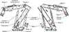 |
Fig. 1. Placement of selected components on the TM200 manipulator. |
Technical data of the TM200 manipulator with platform.
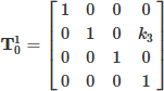
The working space of the TM200 manipulator is expressed using homogeneous transformation matrices, which are as follows:
 (1)
(1)
 (2)
(2)
 (3)
(3)
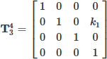 (4)
(4)
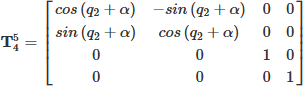 (5)
(5)
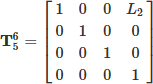 (6)
(6)
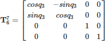 (7)
(7)
 (8)
(8)
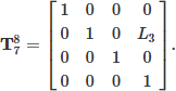
The geometric parameters of the manipulator are shown in Figure 2, where the constants have the following values [mm] and [°]: (k2 = 1890.8; k3 = 220; k1 = 258.3; L1 = 1860; L2 = 1730; L3 = 526.5; α (alpha) = 10.35; q1min = 16.9; q1max = 74.2; q2min = 43.3; q2max = 149.4; q3min = 1 and q3max = 73.72).
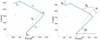 |
Fig. 2. Geometric parameters of the TM200 manipulator. |
The resulting transformation matrix is expressed as the product of all transformation matrices in the order in which the individual transformations of the local coordinate systems were performed.
 (9)
(9)
 (10)
(10)
In this way, the relation of the manipulator’s end effector with respect to the global coordinate system located at the base of the manipulator was expressed. The given mathematical model was simulated in the Matlab environment, which made it possible to obtain the resulting workspace of the manipulator. The workspace of the manipulator is shown in Figure 3, where the X–Y plane is displayed. A more precise depiction of the workspace can be achieved by reducing the step size.
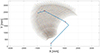 |
Fig. 3. Workspace of the TM200 manipulator in the X–Y plane without tool. |
The main tool used was a circular saw with a basket, equipped with a special saw blade with a diameter of 355.6 mm and a maximum thickness of 2.2 mm. The optimal speed is 1400 rpm, the optimal cutting speed is 1.7 mm/s, and the blade is mounted in a specially designed device. This tool also includes a collecting basket, freely rotatably attached to the lower part of the saw, which also enables automatic emptying of its contents. During the project, several versions of this tool were created, where cutting conditions were tested, and above all the safe capturing of pipe fragments with a maximum length of 700 mm. The final version of the tool is shown in Figure 4, where the left side shows a view of the mounted and covered saw blade. On the right side of the figure, the rotary mechanism and the collecting basket are shown.
 |
Fig. 4. Tool – saw with basket. |
To determine the geometric characteristics of the manipulator, verification tests were also carried out based on the ISO 9283 standard. The following characteristics were selected:
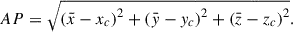
Pose accuracy (AP) – The difference between the programmed position and the mean of the positions actually reached by the actuator’s end effector. The actuator’s end effector must always approach the programmed position from the same direction. The placement of the sensors is implemented in three mutually perpendicular axes (X, Y, Z). From the measured values, the unidirectional position accuracy (AP) in the X, Y, Z axes is calculated according to the following relations:
 (11)
(11)
 (12)
(12)
 (13)
(13)
where (xc, yc, zc) are the programmed values and (xj, yj, zj) are the actual (measured) values.
Where:
 (14)
(14)
 (15)
(15)
 (16)
(16)
The resulting value of the robot’s unidirectional accuracy:
 (17)
(17)
Pose repeatability (RP) – expresses the degree of conformity between the locations of the achieved positions after n repetitions of movement to the same programmed position in the same direction.
From the measured values, the RP value is calculated as the radius of a sphere whose center is the barycenter, according to the following relations:
 (18)
(18)
where,
 (19)
(19)
 (20)
(20)
 (21)
(21)
The coordinates of the barycenter of the achieved points during n repetitions of the same position are calculated according to relations (14–16).
As declared by the ISO 9283 standard, the measurement was carried out at the maximum operating speed used in the workplace (100 mm/s) and at two load values (200 kg–100%; 100 kg–50%). As the measuring component, a precision measuring sphere with a diameter of 60 mm equipped with an internal M20 thread was chosen. The measuring sphere was mounted on an M20 threaded rod, the other end of which was fixed into the thread in the center of the robot’s output flange. Smaller weights and lock nuts preventing the loosening of the measuring sphere were also placed on the threaded rod. The measuring chain consists of three mutually perpendicular Heidenhain MT25 contact sensors equipped with flat contacts, see Figure 5.
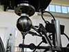 |
Fig. 5. Measuring sphere and placement of sensors. |
The measured data for the unidirectional positioning accuracy of the manipulator were as follows, Table 2: the measured and subsequently calculated AP50 data at half load reached a value of 0.022399 mm. When compared with the required manipulator accuracy of 1 mm, we can state that the robot, after assembly and commissioning, was sufficiently accurate. The average values of the manipulator in the individual X, Y, and Z axes reached an absolute value of at most 0.022267 mm. This value is determined by the design, where the greatest compliance was intended in the Y-axis direction, since this direction corresponds to the anticipated direction of the manipulator’s impact on the steam generator during manual operation.
Calculated values of “Pose accuracy”.
The measured and subsequently calculated AP100 data at full load for the new manipulator reached a value of 0.096706 mm. When compared with the required robot accuracy of 1 mm, we can state that the manipulator, after assembly and commissioning, was sufficiently accurate. The average values in the individual X, Y, and Z axes reached an absolute value of at most 0.075567 mm. This value results from the assumption of increased load in the Z-axis direction relative to the global coordinate system of the manipulator to a doubled value. Since the manipulator’s structure is made of closed steel profiles, the greater weight on the end part causes slight deformation of the manipulator arms.
In Figure 6 a graph of the unidirectional positioning accuracy at half and maximum load is shown.
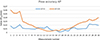 |
Fig. 6. Comparison of the unidirectional positioning accuracy of the manipulator. |
For the calculation of RP, the measured data from the determination of AP were used. By subsequently substituting the obtained data into relations (18 to 21), we obtained the following results, shown in Table 3.
Calculated values of “Pose repeatability”.
In Figure 7 a graph of the unidirectional positioning repeatability at half and maximum load is shown.
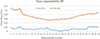 |
Fig. 7. Comparison of the unidirectional positioning repeatability of the manipulator. |
Based on the performed measurements and subsequent calculations according to ISO 9283, we can state that the AP and RP values did not exceed the parameters specified in the robot design. The maximum calculated AP value (0.115318 mm) was lower than the specified value (1 mm). In the case of the maximum calculated RP value (0.077061 mm), this value was lower than the specified value (1.5 mm).
4. Major outcomes
The main differentiating parameters compared to the state of the art are as follows:
-
Higher production efficiency and work productivity, comparable even to flame cutting. The complete fragmentation of a single steam generator (140 tons) took 45 days.
-
A higher level of process automation and intelligent optimization.
-
Minimal radiation exposure for workers.
-
Minimal aerosol generation and reduced spread of contamination to the surrounding environment.
-
Shorter fragmentation time, thereby reducing overall costs (The complete fragmentation of a single steam generator (140 tons) took 45 days).
Feasibility and quality of both inventions was approved in application of prototypes in praxis at successful fragmentation of 12 pieces of steam generators in Nuclear power plant JE V1 in Jaslovske Bohunice (Slovakia), finalized in 2023. Now, in 2024 it is prepared for commercial utilization.
The StarGate fragmentation complex Figure 8 can be used mainly in the disposal of steam generators in decommissioned nuclear power plants, but also in the case of disposal of large heat exchangers or cylindrical tanks contaminated with chemicals, the dispersion of which into the air would be a health or life-threatening hazard.
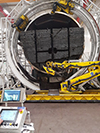 |
Fig. 8. Fragmentation system at NPP JE V1 in Jaslovske Bohunice. |
Due to its unique performance parameters and environmental friendliness, the proposed fragmentation technology is becoming known to the professional public and attracting the attention of world players in the field of decommissioning NPPs. The first reaction was that several experts, not believing that the claimed parameters could be achieved, personally visited the fragmentation workplace with the StarGate system to verify the data. Subsequently, they invited the creators of this system to cooperate in the preparation of bids for decommissioning other NPPs in European countries.
5. Recommendations
-
In current SG fragmentation solutions, it is often evident that cutting technology experts rely on an off-the-shelf robot or roboticists use an off-the-shelf cutting module. However, such approaches do not allow for optimal utilization of the potential in both key components of the technology. Only the synergy of specialists from all key areas can lead to a unique solution whose parameters and properties are “beyond the art”.
-
Initial tests of our first design concepts of shell cutting modules showed that knee-lever structure cannot give requested stiffness at reasonable size of its parts.
6. Final remarks
The interest of customers and the professional public in StarGate results from the current renaissance of the nuclear energy industry.
The number of new NPPs being prepared for construction is increasing, which prompts the acceleration of the process of decommissioning old NPPs, both to create space in established locations for this type of industry, as well as to obtain higher efficiency of electricity production in new NPPs. According to today’s data, there are almost 100 steam generators in the world awaiting fragmentation and further processing (IAEA). And we are ready to serve.
Funding
The project was financed as standard commercial contract without any additional funding.
Conflicts of interest
The authors declare that they have no competing interests to report.
Data availability statement
Data associated with this article can be disclosed upon request through project coordinators, and availability will depend on the request’s objectives and the use foreseen by the applicant
Author contribution statement
L. Vargovcik – Concept design, project administration, supervision, paper structure and writing of generic sections. J. Varga – conceptual and detail design of the shell cutting system, its supervision. J. Semjon - conceptual and detail design of the pipes cutting system, its supervision.
Acknowledgments
The authors thank all project colleagues for their contribution to the work done and the customer for creating excellent conditions for installation and commissioning of the system.
References
- J. Medved, L. Vargovcik, Decommissioning of the A1 NPP heavy water evaporator facility, in ICEM Conference, Reims, France, 2011 [Google Scholar]
- L. Vargovcik, R. Holcer, Increasing Robot Autonomy in Nuclear Application, zborník konf. ROBTEP 2010 [Google Scholar]
- A. Goldenberg, M. Gryniewski, T. Campbell, AARM: A RobotArm for internal operations in nuclear reactors, in 1st International Conference on Applied Robotics for the Power Industry (CARPI), Canada, 2010 [Google Scholar]
- IAEA Bulletin – Nuclear Decommissioning, April 2023, 64, 10 (2023), ISSN 0020-6067, https://www.iaea.org/bulletin/slovakia-sets-global-example-for-nuclear-power-plant-decommissioning [Google Scholar]
- L. Vargovcik, R. Holcer, J. Medved, Mobile robotic systems for fragmentation of nuclear equipment, Appl. Mech. Mater. 282, 116 (2013), Trans Tech Publications, Switzerland [Google Scholar]
- R &D and Innovation Needs for Decommissioning Nuclear Facilities, NUCLEAR ENERGY AGENCY, No. 7191, OECD 2014, https://www.oecd-nea.org/upload/docs/application/pdf/2019-12/719-rd-innovation-needs.pdf [Google Scholar]
Cite this article as: Ladislav Vargovcik, Jozef Varga, Jan Semjon. Robotic system for fragmentation of steam generators (StarGate), EPJ Nuclear Sci. Technol. 12, 9 (2026). https://doi.org/10.1051/epjn/2026001
All Tables
All Figures
|
Fig. 1. Placement of selected components on the TM200 manipulator. |
| In the text | |
|
Fig. 2. Geometric parameters of the TM200 manipulator. |
| In the text | |
|
Fig. 3. Workspace of the TM200 manipulator in the X–Y plane without tool. |
| In the text | |
|
Fig. 4. Tool – saw with basket. |
| In the text | |
|
Fig. 5. Measuring sphere and placement of sensors. |
| In the text | |
|
Fig. 6. Comparison of the unidirectional positioning accuracy of the manipulator. |
| In the text | |
|
Fig. 7. Comparison of the unidirectional positioning repeatability of the manipulator. |
| In the text | |
|
Fig. 8. Fragmentation system at NPP JE V1 in Jaslovske Bohunice. |
| In the text | |
Current usage metrics show cumulative count of Article Views (full-text article views including HTML views, PDF and ePub downloads, according to the available data) and Abstracts Views on Vision4Press platform.
Data correspond to usage on the plateform after 2015. The current usage metrics is available 48-96 hours after online publication and is updated daily on week days.
Initial download of the metrics may take a while.