| Issue |
EPJ Nuclear Sci. Technol.
Volume 11, 2025
Euratom Research and Training in 2025: ‘Challenges, achievements and future perspectives’, edited by Roger Garbil, Seif Ben Hadj Hassine, Patrick Blaise, and Christophe Girold
|
|
|---|---|---|
| Article Number | 20 | |
| Number of page(s) | 16 | |
| DOI | https://doi.org/10.1051/epjn/2025010 | |
| Published online | 16 June 2025 | |
https://doi.org/10.1051/epjn/2025010
Regular Article
Towards improvement of the operation and safety of European nuclear power plants through enhanced thermal-hydraulics experiments and analysis
1
Nuclear Research & Consultancy Group Westerduinweg 3 1755 LE Petten The Netherlands
2
Gesellschaft für Anlagen und Reaktorsicherheit gGmbH Boltzmannstr. 14 85748 Garching Germany
3
EDF R&D – Fluid Mechanics Energy and Environment Department 06 quai Watier 78401 Chatou Cedex France
⋆ e-mail: This email address is being protected from spambots. You need JavaScript enabled to view it.
Received:
15
November
2024
Received in final form:
17
February
2025
Accepted:
18
March
2025
Published online: 16 June 2025
Abstract
Due to the negligible levels of CO2 it produces, nuclear energy is gaining a more prominent role in the current transition to clean energy. An important aspect to nuclear energy generation is the safety of nuclear installations. To ensure safe operation of nuclear reactors, all facets must be carefully monitored and controlled, and the behavior of the operational and safety systems must be assessed in detail under normal and off-normal conditions. A key aspect herein is the reactor thermal-hydraulics, crucial to ensure heat generated in the core gets transferred to the secondary system, during electricity generation, or designated heat sinks, for emergency scenarios. Two European projects focusing on reactor thermal-hydraulics recently received grants within the Euratom to perform four year research that will enhance the operation and safety of the European nuclear power reactors. PASTELS (PAssive Systems: Simulating the Thermal-hydraulics with ExperimentaL Studies) deals with innovative passive safety systems and investigates the possibility of using reliable experimental data to assess the ability of various European thermal-hydraulic tools to simulate the behavior of these systems. GO-VIKING (Gathering expertise On Vibration ImpaKt In Nuclear power Generation), on the other hand, focuses on the hydraulic interaction between the coolant and crucial nuclear power plant components that are susceptible to flow-induced vibrations. Through experimental and numerical investigations, these interactions are further studied and improved modeling methodologies are developed. In the current paper, the global objectives of both projects, as well as the methodologies and the expected impacts are presented. Moreover, selected results are briefly discussed and conclusions are drawn.
These authors contributed equally to this work.
© K. Zwijsen et al., Published by EDP Sciences, 2025
 This is an Open Access article distributed under the terms of the Creative Commons Attribution License (https://creativecommons.org/licenses/by/4.0), which permits unrestricted use, distribution, and reproduction in any medium, provided the original work is properly cited.
1. Introduction
With an ever-increasing demand for energy and the resulting rise in earth's average temperature [1], it is imperative that human kind reduces its dependence on fossil fuels. To this end, over the past years and decades, different sustainable energy solutions have been proposed, developed and even implemented. In order to meet the goal of the Paris Agreement to keep the increase of the long-term global average surface temperature of the Earth well below 2°C above pre-industrial levels and pursue efforts to limit it to 1.5°C, none of the solutions should be discarded. One energy solution recently regaining more attention is nuclear energy. Nuclear energy is a very efficient source of power due to its high energy density per unit mass and volume, meaning a small amount of nuclear fuel can produce a relatively large amount of usable energy [2]. Additionally, it produces negligible levels of CO2 emissions. Therefore, to achieve the goals of the Paris Agreement, nuclear energy is likely to play a significant role. An important precondition to nuclear energy generation is the safety of nuclear installations. To ensure safe operation of nuclear reactors, all facets must be carefully monitored and controlled and the behavior of the operational and safety systems must be assessed in detail under normal and off-normal conditions.
In the early days of nuclear power production, the design and safety assessment of Nuclear Power Plants (NPPs) was mainly based on input obtained from experiments and semi-empirical analyses. This allowed detailed Safety Analysis Reports (SARs) to be produced, demonstrating safe operation of the reactor. While providing valuable data, experiments are costly to perform, and hence cannot be used to assess the functioning of each system or component under all possible conditions. Semi-empirical relations, on the other hand, can provide quick assessments and estimations and can be flexible in use. However, they are often based on simplified representations of the problem at hand. Hence, to guarantee safe operation of the NPPs, especially in the early days, relatively large safety margins were used.
Over time, the state-of-the-art of both experiments and analytical approaches improved, thanks to, amongst others, the evolution of the understanding of the phenomena, improvements of the testing platforms, and modeling capabilities. Regarding the latter, this also included the development of the 1D System Thermal Hydraulics (STH) codes, which are still extensively used today for safety analyses of NPPs. All these developments contributed to reduce the uncertainties in the assessment, and hence reduce the conservatisms considered in the safety demonstration.
Due to the rapid increase on computational power and accuracy of the past decades, numerical tools such as Computational Fluid Dynamics (CFD) and Computational Structural Mechanics (CSM) codes are more frequently used during the design and the safety evaluation and demonstration of NPPs. Further, the traditional System Thermal Hydraulics (STH) codes are extended with 3D fluid modules, which are used in combination with larger and more detailed models of the simulated systems. Such tools can be more readily set up and performed than experiments, while providing detailed information of the complex physics of interest. In addition, design adaptations can readily be tested by modifying the models. Before using the models though, they have to be validated for their intended use, to ensure that they are adequately predictive to be used in design and safety demonstration. Additionally, while different models and approaches of varying accuracy exist, with the most accurate models resolving fine details of e.g., the flow and temperature fields, resolving unnecessary details will result in disproportionately long simulation times. Hence, it is important to know the level of accuracy and modelling that is needed in order to create a quality model of the system or problem that is to be studied. For such validation and accuracy assessment a systematic benchmark of various approaches is important, thereby comparing obtained results with those coming from controlled experiments.
Within the Euratom programme, two projects focusing on the reactor thermal-hydraulics and the associated phenomena in the reactor cooling circuits received grants to perform four years of research on benchmarking numerical models using existing and newly-generated experimental data in order to further enhance the operation and safety of European NPPs. These two projects are PASTELS (PAssive Systems: Simulating the Thermal-hydraulics with ExperimentaL Studies), focussing on designing and implementing passive safety systems and GO-VIKING (Gathering expertise On Vibration ImpaKt In Nuclear power Generation), which aims at improving the design of reactor components against flow-induced vibrations (FIV). Although PASTELS and GO-VIKING rely on different approaches to improve reactor safety analysis approaches, both projects focus on the reactor thermal-hydraulics and the associated phenomena in the reactor cooling circuits. The buoyancy is an inherent quality of the coolant, which is of crucial importance for the design of passive safety systems that are investigated in PASTELS. GO-VIKING deals with impingement of the coolant on slender structures (fuel rods, steam generator tubes) in the plant.
The implementation of innovative passive safety systems is one of the main areas of interest for improving safety being studied by nuclear power plant designers. There has been renewed interest in these innovative systems since the Fukushima Daiichi nuclear accident in 2011 [3]. The affected NPPs relied on an external power source for emergency cooling. This is no longer needed with passive safety systems. In addition, Europe's ambition to become climate neutral by 2050 has opened up new opportunities to step up the electrification of uses in order to help reduce carbon emissions, and in this context, small modular reactors (SMRs) have been identified as credible solutions for replacing fossil-fuel power plants. SMR development strategies are often based on the use of passive safety systems to guarantee the safety of these lower-power reactors, for which the residual heat to be extracted in the event of accident scenarios is lower and therefore requires, theoretically, smaller support systems. However, it remains to be demonstrated that these systems are intrinsically safe and can operate throughout their mission.
The architecture of current electrogenic European reactors (GEN II+/III high-power reactors) incorporates very few of these systems, apart from conventional passive hydrogen recombiners or the EPR core catcher, for instance. European players lack operational feedback on innovative passive systems and it is difficult, even today, to access experimental data on these systems that can be used in good conditions to fully understand their advantages and operating constraints and thus build numerical tools for the design and safety demonstration of these systems. This contrasts with the existing situation for active system, which benefit from several decades of operating experience and which can rely on proven and tested numerical tools. Unfortunately, the range of validity of these codes does not cover all the physical phenomena and conditions of use of these innovative passive safety systems (active systems operating with forced convective flow, at high flowrate and high pressure for instance). If we consider passive systems such as heat exchangers, these are often systems operating on weak driving forces equilibria (e.g. natural circulation), presenting several levels/types of exchanges that can be strongly coupled to each other. They are sensitive to small variation while their operation may vary over time, whether in terms of boundary conditions (pressure, temperature, void ratio, presence of non-condensable gases (NCG)) or flow regime [4]. Even if the knowledge built up in these codes over time remains a solid basis for the simulation of passive systems, it is nevertheless important that these numerical tools are assessed to validate their ability to simulate the specific design of these passive systems with sufficient predictive capabilities. It should also be noted that passive systems are often closed systems and/or have long mission times. Active control systems generally will compensate for small deviations, whereas in open systems, deviations often disappear in fixed boundary conditions with only small simulation errors in some outputs that compensate for each other. For short simulation times, small deviations will often not influence the overall analysis results. For passive systems, these considerations often no longer apply and simulation errors can accumulate rather than compensate for each other.
Vibrations induced by coolant flow, so called flow-induced vibrations, are also particularly important operational and safety challenges. These increase wear and tear and/or material fatigue, and thus have been and remain important contributors to NPP key components’ failures. Such failures can degrade NPP safety features and even lead to a breach of confinement barriers (fuel rod cladding, steam generator tube walls), generating not only operational, but also safety issues. According to the IAEA, grid-to-rod-fretting wear (GTRFW), resulting from such vibrations, was the cause of 58% of fuel failures in PWRs worldwide by 2015 [5]. FIV cause damage also in steam generators (SG). In 2012, a SG tube rupture (SGTR) accident occurred in the San Onofre NPP in USA. An extensive wear of more than 3000 SG tubes was found in its units 2 and 3, leading to primary-to-secondary circuit coolant leaks. The SG in these units were put in operation one year earlier. The principal reason for the extensive wear and the tube damage was found to be related to FIV [6]. Since then, these units are in a shut-down condition pending decommissioning. SGTR, as a result of FIV, has also been observed in many other NPPs in the past [7, 8].
Ageing mechanisms have negative impact on the structural behavior concerning FIV. Over time, material fatigues and wear increases, gaps between the structural components (for example in the reactor pressure vessel) increase, while at the same time the mechanical contacts between the structures degrade. All this makes the nuclear components more prone to vibrations, induced by the working fluid (coolant), which appears to be very important for long-term operation (LTO). Further, in the last decade, many NPPs underwent extensive power uprate programs, some of them even more than one. Such uprates are often realized including, but not limited to, increased thermal power, temperatures and flow velocities, especially in the steam lines. In some cases, these led to increased vibrations in some of the plant components, leading to plant operation at a dramatically reduced power for longer periods [9].
As tests and measurements under operational conditions are often costly or not feasible, prediction of FIV loads by numerical simulation could be a practical solution. The GO-VIKING Horizon Europe project (https://go-viking.eu/) gathers expertise from academia and research organizations, industry, and technical safety organizations (TSO) to synthesize and improve good practices, as well as to generate experimental data and to develop accurate numerical simulation methods [10]. These will support the prediction and evaluation of FIV by EU stakeholders, as well as their decision making on FIV countermeasures in the NPPs.
This paper describes the global objectives of PASTELS and GO-VIKING, as well as the methodologies and the final (PASTELS) and intermediate (GO-VIKING) outcomes and the expected impacts. Some representative results are also presented in a concise form.
2. Thermal-hydraulics investigations and achievements within the Horizon 2020 PASTELS project
2.1. The PASTELS project
The PASTELS project has been proposed to the European Commission (EC) in 2019 following the observation that there was a lack of information available at European level on innovative passive safety systems. Started in September 2020 for a duration of 4 years, the PASTELS project was made up of 11 different partners, 10 of which are involved in the project's experimental and numerical technical objectives. Under the coordination of EDF (France), NPP operator, the project is composed of Technical and Scientific Support Organisation (TSO) with IRSN (France) and GRS (Germany), NPP designer with Framatome GmbH (Germany), Research Centers with ENEA (Italy), CEA (France), PSI (Switzerland) and UJV Rez (Czech Republic), and University with USTUTT (Germany) and LUT (Finland). ARTTIC (France) was part of the consortium assuming the role of Project Management Office (PMO).
2.2. PASTELS objectives
The high-level objective of the project is to enhance the knowledge of European nuclear actors on passive safety systems in order to help European nuclear stakeholders to acquire the knowledge they need to decide whether to implement these systems in new reactor projects, as is the case for high-power reactors such as Westinghouse's AP1000, Rosatom's VVER AES2006 and CNNC's HPR1000, or low-power reactors such as SMRs like NuScale (USA), ACP100 – Lingfong-1 (China) and SMART (Republic of Korea) concepts. This decision necessarily involves the ability to well design innovative passive safety systems, but also to simulate their behavior to support the safety demonstration. The calculation codes for this new industrial application are essential and their validation is based on experimental data calibrated for this need. The PASTELS project has therefore been implemented under two main, experimental and numerical pillars.
2.2.1. Experimental activities
From an experimental point of view, the main objective has been to be able to rely on simple experiments that can be easily simulated by the calculation codes. These new data aim to:
-
gain a deeper understanding of the physical phenomena inherent in passive systems.
-
Identify the dominant parameters for these systems in order to identify those that require the most control.
To enable the project to produce results within the given timeframe, it was important to be able to draw on existing test facilities. In fact, the project is based on existing experimental data provided by ENEA on two different test facilities: HERO-2 [11] and PERSEO [12], located at SIET – Piacenza (Italy). These two test facilities represent what are known as Separate Effects Tests (SET) and Combined Effects Tests (CET), as they aim to focus on a few physical phenomena. On the other hand, more comprehensive test facilities are being used as part of the project. These are the PKL test facility (Framatome GmbH, Erlangen, Germany, [13, 14]), the only experimental facility in operation at the time in Europe that simulates the entire primary side of western-type PWRs in a scale of 1:1 in heights (in 2024, PKL has been dismantled), and on which a dedicated SAfety COndenser (SACO) was implemented during the project, and the PASI test facility (LUT University, Lappeenranta, Finland, [15, 16]) which represents the Passive Containment Cooling System (PCCS) system installed on the VVER AES-2006 based on a containment wall condenser (CWC). Figure 1 provides an overview of the used experimental facilities.
 |
Fig. 1. Experimental means of the PASTELS project. |
The different test matrices in PASTELS have been defined to study different levels of analysis. Quasi-steady tests are carried out to study the impact of key system parameters (pool temperature, pool filling level, pressure and temperature, quantity of NCG, power to be extracted, etc.) while more complex transient scenarios are used to register the different operating regime of passive systems in certain industrial situations. To this end, the start-up and shutdown phases were also measured in order to obtain an overall view of the operation of the systems.
2.2.2. Numerical activities
From a numerical point of view, the aim is to be able to assess the performance of different codes at different modelling scales used by European players operating. The PASTELS project partners have therefore proposed to study tools at system and CFD scales; the thermal-hydraulic part of certain lumped parameter codes for severe accidents has also been evaluated. In addition, a coupled approach between system codes and CFD codes was tested in order to take advantage of the modelling accuracy of CFD codes in certain parts of the simulation domain, while leaving other parts to STH to allow reasonable calculation times. The methodology used by EDF is thermal coupling between CATHARE and neptune_cfd. For example, for the modelling of the SACO, the thermal-hydraulics on the tertiary side (SACO pool) are calculated by neptune_CFD, while the thermosiphon loop on the secondary side (steam generator + interior SACO tubes) is calculated by CATHARE. The methodology consists of supplying the external wall temperature of the SACO calculated by CATHARE to neptune_cfd, which calculates the heat flow using correlations and applies the power density inside the cells coupled to those of CATHARE. The fluid temperature and heat exchange coefficient are then sent back to CATHARE, which can calculate the heat exchange with the SACO pool. This is done at each time step of the calculation.
Table 1 summarizes the different codes used throughout the project, according to experiments and project partners. These codes have been evaluated to identify the strengths and drawbacks of the different approaches for each type of code to simulate the different experiments. The setting of the boundary conditions strongly depends on the ability to transpose/convert the experimental process into accurate boundary conditions for the codes and, therefore, interesting feedback can be provided on the sensitive parameters whose measurements need to be controlled (void measurement at specific points, fluid temperature at different radial positions in the tubes, etc.). The comparison between experimental and numerical results should also focus on the parameters, whose measurements need to be provided for numerical activities with a minimum level of uncertainty.
Details of numerical tools used by the PASTELS consortium, by partners and experiments.
Assuming a sufficient level of confidence in the code results, the in-depth numerical analysis can also provide complementary numerical data not available with the experiments and thus complete our understanding of the physical phenomenon. These numerical activities have been set up using a certain methodology:
-
a code can be used by different partners to simulate the test cases in order to measure the impact of the user effect and to learn from the choices made by the users in terms of boundary conditions to be applied, the need to simulate all or part of the systems studied, the choice of nodalisation (system code), mesh refinement (CFD code), etc.
-
Blind tests are carried out to obtain an initial response from the codes without the possibility of adjusting the input decks, and open tests are then performed to enable sensitivity studies on the models and boundary conditions available and thus identify areas for improvement in the codes.
2.3. Work breakdown structure of the PASTELS project
The PASTELS project comprised five work packages (WPs) in total, with three technical work packages. WP1 and WP5 were devoted to “project management” and “dissemination and communication”. WP2, dedicated to the study of HERO-2 and PERSEO tests, WP3 for studies on SACO and WP4 dedicated to CWC were independent and mainly structured in the same way. For each of these 3 WPs, the activities were scheduled according to the following process: defining the test matrices ⟶ adapting or building the test facilities ⟶ running the tests and analyzing the behavior of the passive systems ⟶ using the data to simulate the test with the various codes ⟶ analyzing the numerical results and, in the case of open tests, improving the input decks and the modelling to replay the test, see Figure 2.
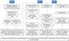 |
Fig. 2. PASTELS work breakdown structure of technical activities. |
2.4. Summary of the activities of WP2, WP3 and WP4
2.4.1. WP2 – SET and CET activities
This WP begins with a bibliographical research to identify relevant information in the literature concerning natural circulation loops with two-phase flow, the main flow regime of the passive systems studied as part of the PASTELS project [17, 18]. More than a hundred articles were examined, as well as a dozen IAEA reports (TECDOC).
Next, the HERO-2 test facility, a single loop where natural circulation establishes a thermosyphon flow, was simulated. In this test facility, a Joule-effect heat source is located at the bottom, while a heat sink pipe immersed in a pool is positioned at the top of the facility. 21 tests with different thermal-hydraulic conditions were made available to the consortium.
The PERSEO installation consists of two loops. The first is an open loop where steam from an external source is condensed in a first basin (the heat exchanger (HX) basin). The second circuit is a closed loop with natural circulation. When the water in the HX pool is heated and vaporised, the steam exits through a steam pipe and is injected into a second pool (the general pool) where it is cooled by direct condensation. There is a connecting pipe with a valve between the two pools at the bottom. When the valve is open, a natural circulation is established between the two pools by gravity when the level of the HX pool is lower than that of the general pool. A single test was made available for the project; the test was split into two parts with, on the one hand, stable conditions to check the behaviour of the system with two different water levels and, on the other, a transient test to check the long-term cooling capacity of the system. Both for HERO-2 [19] and PERSEO [20], the simulations activities were performed in open mode.
2.4.2. WP3 – SACO activities
The SACO operated at PKL as part of the PASTELS project was designed and built on the basis of design discussions between Framatome and GRS. Two series of tests were carried out on this installation. The first is a parameter study used to determine the performance of the SACO for different steady-state parameters (pool filled level, quantity of NCG, core power, pressure and temperature of secondary side, etc.). The second phase introduced a transient scenario (Station Black Out) to demonstrate the functionality of the SACO in an operational environment [21]; this second phase was also complemented by additional parameter studies (level of water in SACO straight tubes), drawing on feedback from the first phase tests, particularly from the point of view of NCG management.
The simulation work consisted of a series of blind and/or open tests, and significant feedback on the modelling of the codes enabled improvements to be made to the modelling of the input decks of the test facility between phase 1 and phase 2.
2.4.3. WP4 – CWC activities
The activities on PASI were based on ten different experiments; eight were again devoted to determining the system's performance for different steady-state conditions (effect of flow resistance, water basin level... for different steam injections) and two transient tests were also carried out to reproduce the system's behavior in an industrial configuration to carry out the test matrix, the test facility was adapted to the needs of the test program (slight modifications). As with the other two technical work packages, open numerical simulations were carried out to assess the code's ability to represent the physics. As part of this work package, a comprehensive study of the different flow regimes identified during the various tests was carried out and led to new models for estimating the intensity and frequency of oscillations generated by the flashing and geysering effect; details of these models can be found in [22].
2.5. Key findings of the PASTELS project
The conclusions of the project have been defined according to several indicators linked to the initial objectives of the project:
-
what is the behavior of the passive systems studied?
-
What lessons have been learned from the tests carried out?
-
What is the maturity of the codes for simulating passive safety systems?
2.5.1. Behavior of the passive systems studied
From the various tests carried out during the project, the first lesson to be learned is that these systems (SACO and CWC) demonstrate their ability to operate with expected performances for the various T/H conditions tested in the project. The PASI loop PCCS with its CWC represents a natural circulation loop open to an atmospheric pool of ambient air. Changes in the T/H conditions of the system (e.g. changes in pool temperature) make the flow in the riser rather unstable, with the appearance of physical phenomena such as flashing and geysering. Nevertheless, overall system performance is little affected by these unstable regimes.
For the different thermal-hydraulic configurations tested on PKL/SACO, the system demonstrated its ability to cool the secondary/primary side as well, despite the presence of NCGs, which can impair condensation-type heat transfer by acting more or less as thermal insulators. In the case of SACO, it was possible to demonstrate stratification of NCG in the tubes at certain times (condensate layer/under a layer of NCG under a layer of steam). This NCG layer was intermittently localised in the tubes in contact with the pool, temporarily blocking thermal exchange. Nevertheless, the SACO has shown a certain ability to self-regulate this phenomenon, as less heat exchange means less condensate, which leads to NCG being localised in parts of the circuit not affected by heat exchange. In the case of SACO, industrial design recommendations were established, such as the need to design systems with tubes long enough to enable the system to operate despite the presence of NCGs, which will be difficult to avoid in an industrial configuration (water hydrolysis, system conditioning deficiency, etc.).
Despite their sensitivity to T/H variations, these systems have proven their robustness in fulfilling their mission. The conditioning of these systems remains probably a key element for the success of these systems that will have to be tested more thoroughly in the near future.
2.5.2. Lessons learned from the tests carried out
Implementing simple and well-controlled experiments was not an easy task and one of the conclusions of the project is that it remains necessary to continue efforts to define test scenarios that can be used by experimenters. Indeed, the translation of test conditions into boundary conditions for calculations is not always obvious and it is necessary to ensure that the tests are sufficiently rigged in terms of type of measurements, measurement localizations, measurement uncertainty, etc., according to the various modelling scales. This conclusion, which seems trivial, requires an important dialogue between experimenters and numerical engineers so that each is aware of the needs of the other. In particular, in the context of the passive systems studied, it is important to master heat losses, pressure losses and non-condensable gas measurements, which are very sensitive parameters for these innovative passive systems and therefore key elements in setting up input decks.
Validation of the scaling of these models and possible distortions remains a key point on which it will also be necessary to continue to progress to ensure that the conditions obtained will be relevant on an industrial scale.
2.5.3. Maturity of the codes for simulating passive safety systems
At the system scale and for severe accident codes, it was possible to demonstrate the ability of the codes to reproduce with a good level of representativeness the main physical phenomena of these systems (the oscillations of the two-phase flows observed in the downcomer of the PCCS of PASI for example, see Figure 3.
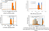 |
Fig. 3. Mass flow rate calculations in PASI test facility downcomer for different codes. |
Depending on the users and the codes, different strategies were used (modeling of the entire system or application of boundary conditions to the interface of the exchangers in certain cases for instance). All these strategies have shown their advantages and disadvantages. In open test mode (which allows to adjust the codes in an iterative way), the codes showed some deviations due to improvable physical models such as heat exchange coefficients for condensation or different levels of fine-tuning for different users to perform post-test calculations. For example, in the case of the SBO test on PKL, the GRS AC2 model only used the experimental boundary conditions of the experiment, e.g. on the pressurizer heating, while in other models, the pressurizer heating and the pressurizer level were controlled and adapted to the experimental values in order to capture the relevant part of the transient. This partly explains the differences in results that can be seen on the right side of Figure 4. A detailed discussion, unfortunately, is beyond the scope of this publication.
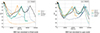 |
Fig. 4. Station Black Out scenarios on PKL test facility (evolution of pressure in the primary circuit) – Benchmarks with various system codes show significant improvements in open mode compared with blind mode. |
In blind test mode, the deviations were significantly greater in particular due to:
-
a poor understanding of the experimental conditions or boundary conditions tainted by uncertainties.
-
Physical models or nodalisation non-adapted. This last conclusion underlines the importance of evaluating the tools on as many blind tests as possible, which remains the only way to assess the predictiveness of the codes, see Figure 4.
Generally speaking, it was not possible at this scale to have common and generic good practices to optimally model each of the experimental models. One important insight was that compounding errors in simulation codes over the long time periods in Figure 4 due to limitations in code models and modelling resolution can be a major challenge if there is no model fine-tuning against experimental data. Additional investigations will be necessary to move towards this objective, which makes it possible to avoid going through a model validation phase again for each modification of the design of the passive systems.
Another element of reflection concerning the simulation of passive systems concerns the availability of input decks. In particular for PKL, the project was able to rely on existing input decks, which had been used in multiple prior validation calculations, thanks to the project partners, which made it possible for this type of integral test facility to consider numerical simulations within the timeframe of the project: starting from scratch would have been really complex.
Dealing with CFD codes and large systems such as passive safety systems remain a challenge, especially due to the much higher cost of the simulation that complicates the verification and validation (V&V) process. Nevertheless, some CFD calculations have been performed and the local approach provided by these codes has proven very useful for a better understanding of specific physics such as the unbalance in the presence of non-condensable gases in SACO tubes or the thermal stratification in the suppression pool of the PERSEO and PKL experiments, see Figure 5.
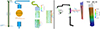 |
Fig. 5. Neptune_cfd simulation – predicted velocity field inside the SACO tubes to visualise the preferential direction of flow (left side) and neptune_cfd/CATHARE thermal coupling with thermal stratification visible in the SACO pool (right side). |
A thermal coupling between the system and the CFD code has been performed. The feasibility has been proven without identifying any direct benefits compared to the system scale alone. Further analyses with tests with a larger local effect in the flow (stratification, cross flow …) still need to be tested to confirm the relevance of this approach.
A summary of the lessons learned from the evaluation of the calculation tools for the passive systems studied in WP2, WP3 and WP4 is available respectively in the documents [23–25].
3. Thermal-hydraulics investigations and achievements within the Horizon 2020 GO-VIKING project
3.1. The GO-VIKING project
The GO-VIKING, coordinated by the Gesellschaft für Anlagen- und Reaktorsicherheit (GRS) gGmbH, Germany and the Nuclear Research and consultancy Group (NRG), The Netherlands, started in June 2022 and will run four years. Its main objectives are to increase the knowledge of reactor-relevant FIV, to develop, improve and validate Fluid-Structure Interaction (FSI) methods for FIV evaluation, and to provide guidelines for the prediction and assessment of FIV phenomena in nuclear facilities. Building on that, it aims to bring them into application at European nuclear stakeholders for improving the design, operation, and maintenance of key NPP components, and thereby, enhance both safety and operation of existing and future NPP in Europe. The mix of 18 partners from research institutes, technical support/safety organizations, universities, power generation industry, vendors, and utilities implies not only a solid knowledge fundament for the common work in GO-VIKING, but it also ensures that the project outcome will reflect the interests and needs of the different partner groups in the nuclear business.
3.2. Specific objectives and concept of the GO-VIKING project
The following GO-VIKING specific objectives (SO) were defined:
SO1: generation of new experimental and high-resolution numerical data, relevant for nuclear fuel assemblies (FA) and steam generators (SG). In order to properly validate and assess the predictive capabilities of numerical tools for simulating FIV of key nuclear steam supply system (NSSS) components, such as FAs and SGs, detailed reference data is needed. The availability of such data is very limited though, because the data is often restricted to single phase flow problems and to structural vibrations measurements. The lack of information on the flow field, responsible for the vibrations, limits the possibility to in-depth analyze the complex formation of the vibration excitation mechanisms. Therefore, in GO-VIKING, single and two-phase FIV experiments that go beyond the current state-of-the art are performed, using amongst others advanced flow measurement techniques. In addition, high-resolution numerical data, based on either Direct Numerical Simulation (DNS) or wall-resolved Large Eddy Simulation (LES) approaches, is being generated to provide extra reference information for the flow field and the vibration inducing forces.
SO2: expanded knowledge on efficiency, accuracy and reliability of FSI methods. The available FSI methods for the evaluation of FIV phenomena can be based on turbulence modelling resolution, one- or two-way data transfer, explicit or implicit coupling schemes, moving or fixed fluid grids, etc. Some of the FSI methods provide sufficient accuracy for a certain type of FIV, while the same can lead to inadequate results when used for other FIV types. Therefore, knowledge on the advantages and disadvantages of the different methods, as well as on the range of their applicability are necessary. GO-VIKING performs cross-validation and benchmarking of different methods and approaches, using experimental and high-resolution numerical data as reference.
SO3: provision of validated fast-running FSI tools with uncertainty quantification (UQ) methods. Within GO-VIKING, high- and medium-resolution FSI methods are being developed, validated, and provided to the European nuclear stakeholders. Since the industry is also in need of fast-running approaches, development, validation and application of practical and efficient FSI methods, based on reduced-order models (ROM), are included in the work program of the project. Such methods also enhance the development and application of uncertainty quantification (UQ) techniques, needed for best-estimate calculations when used as evidence to support safety cases.
SO4: highly increased expertise of and awareness on FIV phenomena in NPPs. The performed experiments together with the numerical analysis of FIV with high-resolution 3D CFD and computational structural mechanics (CSM) tools will allow deeper insights in the FIV formation mechanisms as well as improved understanding of the interplay between fluids and structures. This will lead to a highly increased expertise in the different FIV phenomena that take place in FA and SG. The result will be increased knowledge and awareness of the operators and regulators concerning FIV in NPPs.
SO5: synthesis of best practices and training of stakeholders and graduates in numerical FIV analysis. The expertise, generated within the whole GO-VIKING on the evaluation of FIV in nuclear reactors with the help of validated FSI simulation tools, will be synthesized in Best Practice Guidelines (BPG) on the use of FSI methods for FIV evaluation. These guidelines will help vendors, regulators, TSOs, and industry to obtain a deeper understanding on the FIV nature and their impact on the safety of nuclear reactors, and to provide them with knowledge and confidence in their analysis in this very challenging interdisciplinary field.
3.3. Structure and impact of the GO-VIKING project
The structure of the project is based on eight work packages, as shown in Figure 6. In WP1, the relevant FIV phenomena in NPPs and the available FSI methods are studied, while the needs and expectations of the stakeholders for FSI tools were already identified in a specialized workshop. All important findings and conclusions were provided to the experimental and numerical WPs (WP2–WP5), in which FSI methods and models are developed and validated. WP2 is dedicated to the analysis of single-phase FIV in FA, while WP3 deals with single-phase FIV in cross-flow, relevant to SG. The complex nature of the FIV in multiphase environment will be investigated in WP4, for both FA and SG relevant configurations. The data generated in WP2–WP4, together with conclusions and recommendations, is being used as an input for the development of fast-running methods in WP5. Further, in WP5, UQ methods for FSI simulations are developed. The experience gained in all other technical WPs will be synthesized in BPG on the Use of FSI Methods for the Evaluation of FIV in Nuclear Applications close to the project end. The other three packages deal with training and dissemination (WP6), project management (WP7), and ethics (WP8).
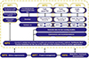 |
Fig. 6. Structure of the GO-VIKING project. |
The GO-VIKING developments and outcome will have an impact on the nuclear reactor safety and operation in Europe. Less leaking FA and SG tubes through improved predictions of FIV phenomena with sophisticated numerical tools will increase the safety of the current reactors in normal operation and decrease the staff exposure in the plants. At the same time, the probability of accidents like SGTR will be decreased. The improved predictive capabilities of the developed FSI methods will also support the vendors to design robust and more reliable nuclear equipment. Improving nuclear reactor safety is beneficial not only for the operators and vendors, but also for the general public in Europe. Major outcome of the GO-VIKING project are high-quality knowledge, scientific methods, and tools beyond the current state-of-the-art that will help the understanding, assessment and reduction of the negative FIV impact on the structural integrity in the components of the ageing power plants. This will support the nuclear operators in Europe to successfully realize their long-term operation (LTO) programs, which in turn, will provide the general public with more carbon-free electricity.
3.4. Selected results of the on-going GO-VIKING project
Due to the limited article length, this subchapter will present only one selected result per technical GO-VIKING WP in very concise form. Additional information can be found in the corresponding project deliverable or literature reference.
3.4.1. WP1 – Literature reviews and the GO-VIKING Stakeholders outreach workshop
Within the WP1, three different literature reviews were carried out: on the available nuclear power plant operational experience with FIV, on the existing experimental data, and on the available FSI methods [26]. It was found that FAs have historically been concerned by fuel leakage with grid-to-rod fretting wear (GTRFW), which is one of the most common causes of fuel failure. GTRFW is generally caused by the axial turbulent coolant flow that exerts fluid forces and eventually rod vibrations with consequent impacts between the rod surface and the spacer grid contact points. In SG, turbulence-induced vibrations and vortex-shedding can result in a long-term fretting wear in the tube-to-support plate and in the tube-to-anti-vibration bar contact regions. In the second literature review, the existing experimental data was analyzed, categorized and presented in a systematic way [27]. It was shown that Turbulence-Induced-Vibrations (TIV), Vortex-Induced-Vibrations (VIV), and Fluid-Elastic Instability (FEI) are the most common FIV mechanisms in reactor relevant geometries. Similar work was done also for the available numerical FSI methods that can be applied for the analysis of FIV. To accurately resolve the pressure fluctuations, scale-resolving methods such as LES or DNS are used on the fluid side, though attempts are being made to use hybrid approaches or URANS solvers with additional models for the pressure fluctuations. On the structural side, most often 3D structural elements are used, but due to the relatively simple geometry of the rods, 1D beam elements and modal decomposition methods have been shown to also give good estimates for the rod's displacement.
The Stakeholders’ Workshop was organized by EDF in collaboration with IRSN in February 2023, in which 14 stakeholders and institutions from Europe and North America attended and presented their relevant topics on FIV [28]. The contents of the presentations ranged from numerical tools used for FIV, needs and expectations in terms of numerical analyses, and to examples of FIV issues encountered recently in the NPPs. During this successful event, the safety authorities and TSOs presented their requirements and recommendations for quality plan, verification and validation of the numerical tools used for the safety demonstration case, as well as the need for supplementary uncertainty quantification analyses to the best estimate simulation results. These requirements and recommendations are taken into account in the work performed as part of the technical WPs.
3.4.2. WP2 – Flow-induced vibrations in fuel assemblies: ALAIN 5×5 rod bundle experiment and first simulation results
The ALAIN experiments [29] had been performed by Framatome GmbH in Erlangen, Germany, with the aim to study complex FIV behavior of different FA designs. The experimental setup is illustrated in Figure 7, left. It represents a reduced 5×5 PWR test FA that was placed in a channel with a square cross-section with a nominal lateral gap between the bundle and test channel of 1.5 mm. The vibration response of the FA was measured using lasers for a wide range of the flow rates. The simulations for this benchmark are performed for the axial flow velocity corresponding to Reynolds number of 90 000, for which LDA flow measurements were also carried out. First, stand-alone CFD simulations using an appropriate medium-resolution and high-resolution modelling approach, based on LES, were performed by Framatome and CEA. The purpose of these simulations was to evaluate the global flow field and the detailed unsteady flow characteristics in the bundle, as well as to assess the requirements for the medium-resolution CFD approaches. CEA conducted RANS and LES simulations on a reduced single span using TrioCFD for fluid flow and the SALOME platform for mesh generation. The high-resolution numerical analysis was based on a mesh with approximately 450 million cells. CEA used standard k-ɛ for RANS and WALE sub-grid scale model for LES with wall models. While mean axial and cross-flow velocities matched well, there were deviations in mean velocity fluctuations. Current work includes addressing FSI effects and improving statistical convergence in LES. The results of these high-resolution simulations will be then compared with the results of the GO-VIKING partners performing medium-resolution simulations (GRS), thus shedding light on the capabilities of the FSI methods, based on different CFD turbulence modelling to predict FIV in nuclear FA. Such knowledge is important also for the fuel assembly design as well as for the further optimization of accident tolerant fuels (ATF).
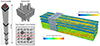 |
Fig. 7. ALAIN 5×5 experiment by Framatome with reduced-length assembly with 23 rods, two guide tubes and several spacer grids (left); LES simulation results, generated by Framatome, showing velocity and wall shear stress magnitudes in the computational single-span CFD domain (right). |
3.4.3. WP3 – Flow-induced vibrations in steam generators: GOKSTAD tube bundle experiment and first simulation results
At VKI, a new experiment named GOKSTAD was designed to generate high-resolution data for single-phase, cross-flow induced vibrations of flexible tubes within a tube bundle. It is a square tube bundle of 7×7 tubes using water as medium, with the aim to perform experiments at a maximum Reynolds number Re = 82 500, higher than what is currently available in the literature. The design is flexible, allowing to vary the number and position of the flexible tubes. Time-Resolved Particle Image Velocimetry (TR-PIV) is used to measure the flow field (mean, fluctuating components, Reynolds stresses), essential for proper validation of the flow solver used in FIV models. Strain gauges are used to measure the fluid forces during the static, i.e., fixed tubes, tests, while accelerometers measure the displacements of the moving tubes in the dynamic tests. Data will be generated for a range of flow velocities and tube configurations (all tubes fixed, one central moving tube, two moving tubes, etc.). The Von Karman Institute (VKI) experimentalists carried out the first measurement campaign used for loop characterization without FSI. The next campaigns with vibrating tube(s) will be started soon. The scientists from Virginia Commonwealth University (VCU) already performed first pre-test simulations with the spectral CFD code Nek5000 [30]. For the selected boundary conditions, it was found that in streamwise direction the flow of the fluid can be observed as “flow channels” through the tube bundles with the highest magnitude of velocity in between the tube columns. However, areas with cross-flow are also present in between the tube rows. The comparison with the experimental data to be generated will reveal the advantages and drawbacks in the application of high-resolution FSI methods for the evaluation of FIV in cross-flow, which are of particular relevance for the safe operation of NPPs with SG as well as plants with heat exchangers in general (see Fig. 8).
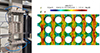 |
Fig. 8. GOKSTAD test section with 7×7 tube array experiment by VKI (left) and high-resolution LES simulation results, generated by VCU [30], showing the streamwise velocity in the computational domain (right). |
3.4.4. WP4 – Flow-induced vibrations in multiphase flows: TITAN tube bundle experiment and first simulation results
The phenomenology of FIV in multiphase flow environment are addressed with several experiments, one of these being TITAN. It is a hydraulic loop, built at CEA, Saclay, to study the FSI between a rotated triangular tube bundle and an air-water cross-flow [31, 32]. The bundle consists of 5×6 rigid stainless-steel tubes with diameter of 30 mm, 300 mm long, and a P/D (pitch/diameter) ratio of 1.44, completed by two rows of half-tubes attached to the test-section walls, see Figure 9, left. A mixer and a rigid bundle with 20 tubes are used to condition the incoming vertical flow before the test section. A sapphire bi-optical probe is introduced in the test section to measure local quantities like number of bubbles, the number of bubbles per unit of time, and the local void fraction. The RMS displacement amplitude is also available. TITAN is characterized with high flow velocities and Reynolds numbers up to 250 000. Each experimental run has been performed with a constant void fraction in the range 0–100%. In some experiments the flow rate is increased until fluid-elastic instability (critical velocity) is reached. EDF and University of Ghent performed first simulations of the TITAN experiment with two different CFD codes – ANSYS Fluent und Nepture_cfd. While the analyses of University of Ghent are based on Volume-of-Fluid (VOF) method [33], the EDF scientists rely on the implemented GLIM (Generalized Large Interface Model) in Neptune_cfd [34]. Both analyses showed that such computations are very challenging and that the void distribution at the inlet of the numerical domain plays an important role for the accuracy of the predictions, and therefore, has to be specified with special care. Figure 9, right, presents the void distribution in the computational domain, calculated with the Neptune_cfd code by EDF. Such computations increase the expertise in the field of the numerical analysis of FIV in multiphase flows, since they provide an in-depth view on the complex interaction between fluids and solids in such environment. These are important not only for boiling water reactors, but also for PWR in off-normal conditions as well as for the upper arc-type U-tube region of the SG. The knowledge gained in this and in the previous work packages will help reducing the length of the European NPP outages as well as the dose of the staff through more robust SG designs with less leaking tubes.
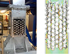 |
Fig. 9. TITAN test section with 5×6 tube array multiphase experiment by CEA (left) and Neptune_cfd results, generated by EDF, revealing the void distribution in the computational domain (right). |
3.4.5. WP5 – Fast-running methods and uncertainty quantification: reduced-order model for the fluid domain
Within GO-VIKING WP5, reduced-order models (ROMs) for the fluid and solid domains are developed and implemented in order to speed-up the FSI computations, while closely reproducing the physics of the full-order models. The AMOVI facility [35] is a small modular and easy-to-maneuver loop aimed at studying cross-flows in tube bundles, operated at CEA. It addresses low-turbulent regimes in a normal-square tube bundle of 3×5 tubes plus two columns of 5 semi-tubes. The diameter of the tubes is 12.15 mm with a P/D ratio of 1.44, values similar to those used in steam generators of NPPs. PIV, LDV and high-speed camera measurements are performed to provide data on the flow pattern inside the test section and the vibration characteristics of the central tube. Experiments were carried out, in which the central tube was flexible, while all others in the bundle were fixed. GRS developed a model of the AMOVI facility within the ANSYS CFX – MOR (Model Order Reduction) code [36]. The MOR approach is a ROM for the structural domain that is based on the mode-superposition method. The latter uses the natural frequencies and mode shapes from a modal analysis to characterize the dynamic response of the structure of interest to transient or steady harmonic excitation. In combination with ANSYS CFX it allows a reduction of the total computational time, compared to the full-order model in ANSYS CFX-Mechanical. Figure 10 shows the velocity distribution in the AMOVI bundle (left) and the calculated tube vibration frequency (right), which deviates by just 1 Hz from the measured value. High-resolution simulations of this experiment are performed at EDF in France [37] and other institutions. The benchmark between the high-resolution and fast-running simulations and the comparison with experimental data will reveal the potential of ROM to provide reliable results for FIV at significantly lower cost. The large computational time, necessary for such analyses, is one of the main bottlenecks in the numerical evaluation of the vibration phenomena. Therefore, the work in WP5 is of great importance for the nuclear industry, which is interested in getting timely solutions for a particular issue in the plants.
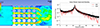 |
Fig. 10. Velocity distribution in the AMOVI tube bundle (left) and frequency response of the central vibrating tube (right), calculated by GRS. |
WP5 deals also with UQ. University of Ghent identified the Polynomial Chaos Expansion (PCE) method as appropriate UQ method in the frame of FIV analyses. The advantage of PCE over other UQ methods is its low computational cost [38]. PCE was tested first on a steady case without FSI, such that creating a Monte Carlo benchmark was feasible. From the comparison it was concluded that valid results were obtained using PCE and that the method converges sufficiently fast in terms of polynomial order. Currently, the method is being applied for the TITAN experiment.
The Technical University Delft explores the Bayesian framework as it pertains to calibration and inverse problems in the context of CFD codes, particularly RANS turbulence modelling. The major value of this framework lies in its ability to precisely characterize relationships between arbitrary inputs, outputs, and state variables of complex computational models. The power of the Bayesian framework comes from representing relationships between variables in terms of joint probability density functions. However, this generality comes with significant computational cost [38]. Therefore, the Dutch scientists explore large class of variational methods for the application of this method for a FIV case.
4. Conclusion
The current paper describes perspectives and results of the Euratom projects that aim at improving the operation and safety of European NPP through enhanced thermal-hydraulics experiments and analysis, viz. the PASTELS, focusing on the thermal-hydraulics of passive safety systems, and the GO-VIKING project that assesses FSI in nuclear reactor components susceptible to FIV.
During the PASTELS project, the various objectives defined at the start of the project were achieved. Firstly, a large and well-documented experimental database has been developed on two passive systems of interest: SACO and CWC. The project's experimental observations have provided important information on the physical behavior of these systems under various thermal-hydraulic conditions, with particular emphasis on mechanisms that could reduce heat transfer efficiency. Further evidence was obtained on the feasibility of relying on the performance of SACO and CWC, which has been shown to meet expectations despite system oscillations (PASI, as long as there is water storage in the loop) or the presence of NCGs (PKL, as long as the exchange surface is not completely affected).
From a numerical aspect, the systems and severe accident codes have shown their good potential for reproducing physics; they have proved to be fairly reliable, provided they are given the right information. Nevertheless, certain physical models could still be improved, such as heat transfer by condensation and they will need to continue to be evaluated in more blind conditions to guarantee their predictiveness and robustness. The CFD or CFD-system coupling approach still needs to be developed/studied before it can be used on an industrial scale, but it is an interesting complementary approach for the detailed analysis of these systems.
Finally, new models were developed during the project as analytical models to estimate the intensity and frequency of oscillations generated during PASI operation by the flashing and geysering effect; these new models could help to design systems with operating conditions as close as possible to steady-state flow regimes. In the future, it is likely that the large amount of experimental data obtained will continue to be used in the code validation database; it represents an interesting source for progress in the validation of codes for passive safety systems.
Within GO-VIKING project, experimental and numerical activities are combined to: (i) increase the experimental database of FIV inside NPPs; and, (ii) improve the existing capabilities of the numerical tools to simulate and predict these phenomena. The project's structure and expected impacts were briefly presented. Two and a half years after the GO-VIKING Kick-Off Meeting in at GRS in Garching, Germany, the project enters its most productive phase without delays and is well on track with all deliverables and milestones scheduled so far being delivered. Illustrative results from each work package were presented in a very concise form, showing the progress that is being made in the first half of the project duration. The commitment of all GO-VIKING partners is substantial for the good project progress and keeping this pace in the up-coming years will guarantee its success. The GO-VIKING developments and outcome will have an impact on nuclear reactor safety and reactor operation in Europe. Less leaking FA and SG tubes through improved predictions of FIV phenomena with sophisticated numerical tools will increase the safety of the current reactors in normal operation and decrease the staff exposure in the plants.
Funding
The described activities are funded by the European GO-VIKING project under Grant Agreement No. 101060826 and the European PASTELS project under Grant Agreement No. 945275.
Conflicts of interest
The authors declare that they have no competing interests to report.
Data availability statement
A large majority of the deliverables produced as part of the PASTELS and GO-VIKING project are public documents. They are available on projects’ official websites at https://www.pastels-h2020.eu/page/en/media-center.php (PASTELS) and https://go-viking.eu/ (GO-VIKING).
Author contribution statement
Conceptualization, Data curation, Formal analysis, Funding acquisition, Investigation, Methodology, Project administration, Resources, Supervision, Validation, Verification, Visualization, Writing – original draft, Writing – review & editing: – K. Zwijsen, A. Papukchiev, M. Montout
References
- IPCC (Intergovernmental Panel on Climate Change), AR6 Synthesis Report: Climate Change 2023, Technical Report, 2023 [Google Scholar]
- J.B. Lamarsh, A.J. Baratta, Introduction to Nuclear Engineering, 3rd edn. (Prentice Hall, 2001) [Google Scholar]
- IAEA, Design Safety Considerations for Water Cooled Small Modular Reactors Incorporating Lessons Learned from the Fukushima Daiichi Accident, TECDOC 1785, IAEA, Vienna, 2016 [Google Scholar]
- IAEA, Progress in Methodologies for the Assessment of Passive Safety System Reliability in Advanced Reactors, TECDOC 1752, IAEA, Vienna, 2014 [Google Scholar]
- IAEA, Review of fuel failures in water cooled reactors (2006–2015). IAEA No NFT-2.5, NE1864 (2019) [Google Scholar]
- NRC (2015), https://www.nrc.gov/docs/ML1501/ML15015A419.pdf [Google Scholar]
- K. Kotthoff, Erkenntnisse aus dem Ablauf ausländischer Vorkommnisse mit Dampferzeuger-Heizrohrbruch, GRS, Tech. Mitt. 77, 1 (1984) [Google Scholar]
- P.E. MacDonald, V.N. Shah, L.W. Ward, P.G. Ellison, Steam Generator Tube Failures, NUREG/CR-6365 INEL-95/0383 (1996) [Google Scholar]
- H. Lundqvist, How Things Can Go Wrong, High Vibration Levels in Steam Lines, GO-VIKING Stakeholders’ Workshop, February 16th, 2023, EDF, Paris, France [Google Scholar]
- A. Papukchiev, K. Zwijsen, D. Vivaldi, H. Hadžić, S. Benhamadouche, W. Benguigui, P. Planquart, The European GO-VIKING project on flow-induced vibrations: overview and current status, Kerntechnik 89, 2 (2024), https://doi.org/10.1515/kern-2023-0126 [Google Scholar]
- M. Polidori, P. Meloni, C. Lombardo, A. Achilli, C. Congiu, G. Cattadori, Test Campaign and RELAP5 Post-Test Analysis on the Bayonet Tube HERO-2 Component, in Proceeding of 2019 International Congress on Advances in nuclear Power Plants (ICAPP’19), Juan-les-Pins, France, 2019, May 12–15 [Google Scholar]
- A. Achilli, G. Cattadori, R. Ferri, M. Rigamonti, F. Bianchi, P. Meloni, PERSEO Project: Experimental Facility Set-Up and RELAP5 Code Calculations, in Proceeding of 2nd EMSI and 40th European Two-Phase Flow Group Meeting, Stockholm, Sweden, 2002, June 10–13 [Google Scholar]
- K. Umminger, L. Dennhardt, S. Schollenberger, B. Schoen, Integral Test facility PKL: experimental PWR accident investigation, Sci. Technol. Nucl. Install. 2012, 1 (2012) [CrossRef] [Google Scholar]
- PASTELS project, Deliverable D3.1: PKL & SACO Technical Description & Design Review Report, 2020, https://www.pastels-h2020.eu/ [Google Scholar]
- V. Kouhia, V. Riikonen, O.-P. Kauppinen, J. Telkkä, J. Hyvärinen, PASI – a test facility for research on passive heat removal, Nucl. Eng. Des. 383, 1 (2021), https://doi.org/10.1016/j.nucengdes.2021.111417 [CrossRef] [Google Scholar]
- PASTELS project, Deliverable D4.2: PASI facility description for PASTELS (2021), https://www.pastels-h2020.eu/ [Google Scholar]
- IAEA, Passive Safety Systems and Natural Circulation in Water Cooled Nuclear Power Plants, 2009 [Google Scholar]
- PASTELS project, Deliverable D2.1: Bibliographic research on the phenomena related to the natural circulation in closed loop (2021), https://www.pastels-h2020.eu/ [Google Scholar]
- PASTELS project, Deliverable D2.2: Description of HERO-2 facility and simulations (2022), https://www.pastels-h2020.eu/ [Google Scholar]
- PASTELS project, Deliverable D2.3: Simulation of PERSEO experiments (2023), https://www.pastels-h2020.eu/ [Google Scholar]
- O.S. Al-Yahia, I. Clifford, H. Ferroukhi, Assessment of TRACE code for modeling of passive safety system during long transient SBO via PKL/SACO facility, Nucl. Eng. Technol. 56, 2893 (2024), https://doi.org/10.1016/j.net.2024.02.050 [CrossRef] [Google Scholar]
- P. Dené, M. Montout, E. Garcia, J. Telkkä, V. Riikonen, F. David, Frequency and amplitude of flashing-induced instability in an open natural circulation loop, Nucl. Eng. Des. 424 (2024) [Google Scholar]
- PASTELS project, Deliverable D2.4: Synthesis on the status of code validation on separate (SET) and coupled effect tests (CET) (2024), https://www.pastels-h2020.eu/ [Google Scholar]
- PASTELS project, Deliverable D3.6: Advances on SACO design and related models (2024), https://www.pastels-h2020.eu/ [Google Scholar]
- PASTELS project, Deliverable D4.6: Advances on safety CWC design and related models (2024), https://www.pastels-h2020.eu/ [Google Scholar]
- D. Vivaldi, A. Papukchiev, K. Zwijsen, M. Hussain, W. Benguigui, S. Benhamadouche, Flow-induced vibrations in nuclear power plants, GO-VIKING Deliverable D1.2, https://go-viking.eu/results [Google Scholar]
- W. Benguigui, S. Benhamadouche, F. Beltran, M. Hassan, Experimental and numerical contributions on flow-induced vibration in steam-generator-like tube bundles: A review, Nucl. Eng. Des. 424, 113305 (2024) [CrossRef] [Google Scholar]
- D. Vivaldi, S. Benhamadouche, Report on industry needs and regulatory expectations in terms of tools and methods for FIV analysis, GO-VIKING Deliverable D1.1, https://go-viking.eu/results [Google Scholar]
- H. Hadžić, M. Ren, B. Dressel, D. Tumbajoy Spinel, M. Quenehen, B. Painter, H. Marr, K. Duggan, Numerical Simulation of Flow-Induced Vibration of Nuclear Fuel Assemblies, in Proceedings of the NURETH-20 conference, Washington, USA, August 20–25 (2023) [Google Scholar]
- T. Franklin, L. Carasik, Preliminary LES of cross flow in the GOKSTAD experimental tube bundle, in Proceedings of the ANS Annual Meeting, Las Vegas, USA, June 16–19 (2024) [Google Scholar]
- R. Lagrange, D. Panunzio, TITAN experiment: presentation of the data, GO-VIKING Deliverable D4.5, https://go-viking.eu/results [Google Scholar]
- P. Piteau, X. Delaune, D. Panunzio, R. Lagrange, J. Antunes, Experimental investigation of in-flow fluidelastic instability for rotated triangular tube bundles subjected to single-phase and two-phase transverse flows, J. Fluid. Struct. 123, 104005 (2023), https://doi.org/10.1016/j.jfluidstructs.2023.104005 [CrossRef] [Google Scholar]
- H. Dolfen, J. Degroote, A synthetic bubble model as inlet for fluid-structure interaction simulations with two-phase flow, in Proceedings of The 9th European Congress on Computational Methods in Applied Sciences and Engineering (ECCOMAS) Congress 2024, Lisboa, Portugal, June 3–7 (2024) [Google Scholar]
- W. Benguigui, F. Beltran, Local-scale numerical simulation of an air-water flow in a tri-angular tube bundle in rigid and flexible configurations for different flow patterns, in Proceedings of Pressure Vessels & Piping Conference, Montreal, Canada, July 20–25 (2025) [Google Scholar]
- J. Cardolaccia, F. Baj, An experimental study of fluid-structure interaction in basic in-line arrangements of cylinders, in Proceedings of the Pressure Vessels and Piping Conference, Boston, USA, July 19–23 (2015), https://doi.org/10.1115/PVP2015-45311 [Google Scholar]
- A. Papukchiev, H. Mistry, J. Herb, Flow-induced vibrations in nuclear steam generators: simulation of the AMOVI experiment with different FSI approaches, in Proceedings of the NUTHOS-14 conference, Vancouver, Canada, August 25–28 (2024) [Google Scholar]
- S. Benhamadouche, Wall-resolved LES combined to ALE for predicting flow-induced vibrations of a single flexible tube at different Reynolds numbers, in Proceedings of Pressure Vessels and Piping Conference, Montreal, Canada, July 20–25 (2024) [Google Scholar]
- J. Degroote, H. Dolfen, R. Dwight, A. Eidi, Development of UQ approaches for FIV analyses, GO-VIKING Deliverable D5.3, https://go-viking.eu/results [Google Scholar]
Cite this article as: Kevin Zwijsen, Angel Papukchiev, Michaël Montout. Towards improvement of the operation and safety of European nuclear power plants through enhanced thermal-hydraulics experiments and analysis, EPJ Nuclear Sci. Technol. 11, 20 (2025). https://doi.org/10.1051/epjn/2025010.
All Tables
Details of numerical tools used by the PASTELS consortium, by partners and experiments.
All Figures
|
Fig. 1. Experimental means of the PASTELS project. |
| In the text | |
|
Fig. 2. PASTELS work breakdown structure of technical activities. |
| In the text | |
|
Fig. 3. Mass flow rate calculations in PASI test facility downcomer for different codes. |
| In the text | |
|
Fig. 4. Station Black Out scenarios on PKL test facility (evolution of pressure in the primary circuit) – Benchmarks with various system codes show significant improvements in open mode compared with blind mode. |
| In the text | |
|
Fig. 5. Neptune_cfd simulation – predicted velocity field inside the SACO tubes to visualise the preferential direction of flow (left side) and neptune_cfd/CATHARE thermal coupling with thermal stratification visible in the SACO pool (right side). |
| In the text | |
|
Fig. 6. Structure of the GO-VIKING project. |
| In the text | |
|
Fig. 7. ALAIN 5×5 experiment by Framatome with reduced-length assembly with 23 rods, two guide tubes and several spacer grids (left); LES simulation results, generated by Framatome, showing velocity and wall shear stress magnitudes in the computational single-span CFD domain (right). |
| In the text | |
|
Fig. 8. GOKSTAD test section with 7×7 tube array experiment by VKI (left) and high-resolution LES simulation results, generated by VCU [30], showing the streamwise velocity in the computational domain (right). |
| In the text | |
|
Fig. 9. TITAN test section with 5×6 tube array multiphase experiment by CEA (left) and Neptune_cfd results, generated by EDF, revealing the void distribution in the computational domain (right). |
| In the text | |
|
Fig. 10. Velocity distribution in the AMOVI tube bundle (left) and frequency response of the central vibrating tube (right), calculated by GRS. |
| In the text | |
Current usage metrics show cumulative count of Article Views (full-text article views including HTML views, PDF and ePub downloads, according to the available data) and Abstracts Views on Vision4Press platform.
Data correspond to usage on the plateform after 2015. The current usage metrics is available 48-96 hours after online publication and is updated daily on week days.
Initial download of the metrics may take a while.