| Issue |
EPJ Nuclear Sci. Technol.
Volume 11, 2025
Euratom Research and Training in 2025: ‘Excellence and Innovation in the Nuclear Sector’ - edited by Roger Garbil, Seif Ben Hadj Hassine, Patrick Blaise, and Christophe Girold
|
|
|---|---|---|
| Article Number | 42 | |
| Number of page(s) | 8 | |
| DOI | https://doi.org/10.1051/epjn/2025036 | |
| Published online | 15 August 2025 | |
https://doi.org/10.1051/epjn/2025036
Regular Article
Design and experimental assessment of an innovative vacuum end-effector for irradiated graphite handling
Politecnico di Milano, Department of Energy, Nuclear Engineering Division, Via La Masa 34, Milan, 20156
Italy
* e-mail: This email address is being protected from spambots. You need JavaScript enabled to view it.
Received:
14
April
2025
Received in final form:
27
May
2025
Accepted:
27
June
2025
Published online: 15 August 2025
Abstract
The decommissioning of graphite-moderated nuclear reactors presents considerable obstacles, primarily due to the handling of large volume of irradiated graphite that must be safely extracted and managed. In response to these difficulties, this work focuses on the design and validation of a novel vacuum-based system specifically engineered for the brick-by-brick retrieval of graphite components during reactor decommissioning. The proposed solution aims to overcome limitations of earlier methods, particularly those related to graphite cracking and the generation of secondary waste. The system developed is a proprietary end-effector that enhances suction-based lifting, achieving up to seventeen times increase in lifting power compared to existing industrial counterparts. This design has undergone testing and experimental trials under diverse operating conditions, replicating the handling of Magnox graphite blocks. The system’s capabilities were assessed using key performance indicators such as lifting strength, safety margin, and adaptability under different operational scenarios. Results demonstrated a safety factor of 7 and the capability to lift damaged and broken blocks. The system also proved effective under less-than-ideal airflow conditions, maintaining high safety standards and demonstrating its robustness for real-world decommissioning tasks.
© F. Chebac et al., Published by EDP Sciences, 2025
 This is an Open Access article distributed under the terms of the Creative Commons Attribution License (https://creativecommons.org/licenses/by/4.0), which permits unrestricted use, distribution, and reproduction in any medium, provided the original work is properly cited.
1. Introduction
Although several types of nuclear reactors have been successfully dismantled, graphite-moderated reactors continue to present unique and complex challenges. Widely deployed across Europe throughout the 20th century, these reactors are generally larger and more intricate than their light-water counterparts [1]. At their core lies an array of approximately 40 000 graphite bricks, amounting to a total of 2000 to 3000 tons per reactor, which serve as the moderator and must eventually be extracted. Estimates indicate that decommissioning efforts across Europe, United States, and Asia will require the removal of around 300 000 tons of irradiated graphite blocks [2, 3]. Over 100 [4, 5] research and commercial reactors utilize this technology, and the volume of graphite requiring disposal is expected to rise significantly in the coming decades [6]. In fact, the urgency of this issue within the European Union has led to the establishment of the Horizon 2020 project Inno4Graph [7]. To date, no technology has been able to consistently meet the strict safety standards necessary to reliably extract these blocks [8]. The core difficulty lies in the fragile nature of graphite, which becomes even more brittle under prolonged radiation exposure. Current industrial gripping solutions either lack the necessary lifting strength or tend to damage the blocks during handling. The combination of this brittleness, radiation-induced degradation, and the constrained geometry within the reactor core makes block retrieval an especially difficult task. Efforts to create a standardized, cost-effective and technically feasible decommissioning method have so far been unsuccessful. Friction-based gripping technologies, like those examined in [9], raise concerns about triggering crack propagation in the already weakened graphite, potentially compromising its structure during extraction. Other strategies, such as nibbling or vacuum-based approaches, have shown faster operational times [10], but often at the expense of increased secondary waste production, a trade-off that is environmentally, logistically, and economically problematic. Considering these challenges, this section introduces the concept and development of a novel vacuum-assisted graphite retrieval system. This system seeks to resolve the limitations of previous methods by enhancing safety, minimizing damage to the graphite blocks, and reducing secondary waste generation, thereby enabling a more direct and efficient path to final disposal.
2. Vacuum system design
2.1. Standard vacuum systems
In vacuum-based lifting systems, both the geometry of the components and the direction in which forces are applied play a role in determining overall effectiveness. When applied to the specific case of graphite block retrieval, constraints in physical access necessitate scenarios where suction cups are positioned vertically, and lifting forces are likewise applied along the vertical axis, generating a shear loading onto the component. To estimate the performance requirements of such system, the relevant calculations focus on the vertical orientation of both the suction interface and the applied force. In this context, the theoretical vertical force can be expressed as [11]:
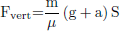 (1)
(1)
In this formulation, m represents the mass of the graphite block, while μ, set at 0.1 for lubricated contact surfaces, denotes the coefficient of friction. The safety factor S is assumed to be 3, g is the gravitational acceleration, and a is the system’s acceleration, which is zero under constant velocity conditions. Using the Latina Magnox graphite blocks as a case study (where m = 57.4 kg), the required vertical lifting force is calculated to be approximately 17 kN. However, the maximum shear load that can be applied, given the vacuum level achievable, corresponds to half the normal force exerted by the suction system, illustrated in Figure 1. Even under ideal conditions, where the full internal contact surface with the graphite is utilized, this results in a peak vertical lifting force of around 13 kN. This value falls short of the force needed for secure extraction. The normal force, in turn, is determined using the following relationship:
 (2)
(2)
where P is the pressure and A is the contact area of the suction cup.
 |
Fig. 1. Suction cup vertical force with respect to its normal force on a friable material like graphite. |
2.2. Graphicore vacuum system
Given the limitations of conventional vacuum systems, which are unable to provide the necessary safety margins for lifting irradiated graphite blocks, a design optimization effort was undertaken. This process involved testing multiple suction cup prototypes and refining their geometry and internal structure to enhance overall performance. One of the main aspects explored was the external shape of the suction cups. Experimental testing revealed that a classic circular suction cup with a reduced contact area provided the best performance when interfacing with concave graphite surfaces. A 30 mm diameter suction cup, specifically the Schmalz PFYN 30 NBR-55 G1/8-AG model [12], was identified as offering the optimal balance between design simplicity and functional efficiency. In parallel, attention was given to enhancing the suction cup friction. An initial approach involved lining the inside of the cup with abrasive materials. While this method showed early promise in qualitative tests, performance rapidly declined as graphite dust accumulated, forming a paste-like residue that negated the increased friction and returned the grip effectiveness to baseline levels. A more successful strategy consisted in enhancing the suction cup internal structure, while making sure a sufficient contact area between the rubber and the graphite walls was always provided. This solution also proved to be robust and reusable, as its performance remained consistent even with prolonged exposure to graphite dust, which did not impede gripping capability. After completing qualitative evaluations, quantitative tests were carried out to assess the lifting performance of the modified suction cups. The setup is shown in Figure 2. These trials involved attaching an array of both standard and enhanced suction cups to a mock-up graphite block designed to replicate the internal geometry of a Magnox reactor. Incremental force was applied to simulate the extraction process while the number of suction cups was progressively increased to mark the difference in performance. A dynamometer was employed to measure the shear load and store data. The results, presented in Figure 3, revealed a fourfold increase in lifting capacity for the modified suction cups compared to their unmodified counterparts. Each modified suction cup was able to sustain approximately 40 N of shear load. This marked improvement demonstrates the effectiveness of the design modifications and validates their potential for use in graphite block extraction. The suction system, including the modified end-effector and the associated process, was patented with PCT extension.
 |
Fig. 2. First arm testing with an array of modified suction cups. The dynamometer can be seen on the right, while the graphite block on the left is dimensioned to emulate the bore of blocks from Latina Magnox reactor. |
 |
Fig. 3. Lifting capability comparison between standard industrial and modified suction cups. The first version showcases a fourfold increase in lifting capability. |
Moreover, increasing the number of suction cups led to a linear growth in total lifting capacity, with a R2 exceeding 0.99. Based on this correlation, it was estimated that approximately 60 suction cups would achieve a safety factor of 3.9 when handling octagonal graphite blocks. The same configuration would provide an even higher safety factor, approximately 7.3, for the square-shaped Magnox blocks (Tab. 1). These findings laid the groundwork for the development of the first physical mock-up of the complete extraction system. The design process evolved from initial conceptual models used in digital simulations to a more refined and realistic prototype, as illustrated in Figure 4.
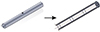 |
Fig. 4. Graphite retrieval unit end-effector design evolution from a model used for multi-body simulation to the concept adopted for the first mock-up. |
Safety factors for standard and modified vacuum system.
2.3. Suction cup upgrade
Following the results achieved with the modified suction cups, attention shifted to optimizing their internal geometry. With the new configuration, a single suction cup was able to lift on average 17 kg under shear loading, while under the application of a normal force of approximately 3 kg on top of the standard normal force determined by equation (2). Given that the final prototype incorporates pneumatic pistons combined with a spring mechanism to maintain consistent contact between the suction cups and the graphite surface, the applied test conditions are considered representative of real operating scenarios. Figure 5 presents the results obtained from the experimental campaign.
 |
Fig. 5. Result of the experimental campaign of the second version of the suction cup design, increasing the lifting capability fourfold compared to the first version and 17 times more than an industrially available suction cup. |
3. Full system testing
3.1. First mock-up test
The initial version of the complete extraction system was developed prior to the enhancement of the suction cup design. This setup, engineered to theoretically achieve a safety factor of 3, consists of three independent arms, each outfitted with 20 suction cups. All arms are connected to a central vacuum pump, forming a unified system. To assess how different airflow rates affect performance, two vacuum pumps were tested: the DA.4 m9602006 model by DVP Technology, with a flow rate of 4 m3/h, and the VE 2100 model by R.A.T, which offers a significantly higher flow rate of 16.8 m3/h. A vacuum gauge was installed at the end of the pipeline, just before the pump, to continuously monitor vacuum pressure during operation. Ideally, each suction cup would operate with an individual airflow of 1 m3/h. However, due to financial constraints, the actual flow available per suction cup ranged from three to fifteen times lower than this optimal value, depending on the pump in use. Testing was conducted by suspending the system from a crane, with a mock-up graphite block attached to a dynamometer (Anyload model OCSL). After activating the vacuum system, each arm was brought into contact with the inner surface of the graphite block. Within 30 seconds, sufficient vacuum levels were achieved, enabling the block to be lifted. The graphite specimen used in testing weighed 10 kg in its base configuration, but additional weights were progressively added to reach a total of 175.5 kg. These incremental loads were used to evaluate the integrity and robustness of the vacuum seal under stress. Tests were conducted on both an intact block and one with structural damage. Moreover, the effect of applying a specialized coating, like the one used in the decommissioning of the Gleep reactor [13, 14], was also investigated. The coating selected was DeconPeel Nuclear 5000 [15], previously analysed by Mazzi et al. [16]. It was chosen due to its proven effectiveness in reducing dust dispersion during decommissioning operations. Being non-toxic, water-based, and fast-curing, the coating supports safe handling without interfering with workflow efficiency. Technical specifications of the product are detailed in Table 2, while Figure 6 shows a front view of the mock-up employed in these tests.
DeconPeel coating parameters
 |
Fig. 6. Full system mock-up, consisting of three arms each with its dedicated vacuum line. |
A snapshot of the testing procedure is shown in Figure 7. The experimental data, summarized in Table 3, demonstrate that the system consistently achieved a safety factor above 2.6 across all tested configurations. In one test, the safety factor reached exactly 3 before system failure occurred. Remarkably, when using the configuration that included the specialized coating, no failure was observed, even under the highest load applied, and vacuum levels remained stable throughout. This outcome indicates that the safety factor in the coated configuration is likely to exceed 3 by a significant margin. Additionally, the system coupled with the coating consistently registered the lowest vacuum level during operation, suggesting that both the surface treatment and the modified suction cup design contribute positively to vacuum performance. Tests conducted with pristine graphite blocks revealed an estimated 10–15% increase in lifting capacity. This improvement is likely due to the lower porosity of the undamaged graphite, which enhances the quality of the vacuum seal. Interestingly, variations in flow rate between the two pumps used during testing did not significantly affect performance, most likely because both flow rates remained well below the system’s optimal design parameters.
Mock-up test results in different configurations.
 |
Fig. 7. Snapshot of the mock-up test with dynamometer screen highlight. |
3.2. Prototype test
The current prototype was developed following the suction cup optimization, which significantly improved the overall performance of the system. As a result, the total number of suction cups was reduced from 60 to just 12, leading to substantial savings in both cost and development time. Engineering system with 60 suction cups would have presented considerable complexity, whereas the improved efficiency allowed for a more compact and manageable design. The device operates pneumatically and was developed through iterative CAD modelling, refined to meet specific manufacturing requirements. The 12 suction cups are arranged into three independent groups of four. Each group can be extended and retracted, facilitating insertion into the graphite block’s bore. This modular configuration also enhances operational reliability: if one group fails to establish a vacuum, the remaining groups can still function autonomously. An additional safety feature was integrated in the form of mechanical support arms, designed to prevent accidental release of the graphite block in the event of a power failure or vacuum loss. These arms retract pneumatically during engagement and passively return to their open position once the block is lifted. The default open-state configuration ensures that the safety mechanism functions regardless of the system’s power status. Figure 8 illustrates a cross-sectional view of the final prototype’s piston. The integrated spring mechanism allows the piston to expand in the absence of air pressure within the system, thereby ensuring continued gripping capability even in the event of a complete power failure. The prototype operates using compressed air at 6 bar and is equipped with one ejector per suction cup group to generate the vacuum. The three ejectors combined provide a total flow rate of approximately 12 m3/h, meeting the operational requirement of 1 m3/h per suction cup. Both the prototype and the CAD model are reported in Figure 9.
 |
Fig. 8. CAD cross-section of the piston which actuates the suction cups movement. The green rectangle marks the location of the spring |
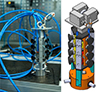 |
Fig. 9. Final prototype and corresponding CAD model. In the upper section, two of the three suction cup groups are visible, while the lower section shows the integrated safety arms. In the CAD model, the upper area accommodates the three vacuum ejectors, which, in the physical prototype, are positioned slightly further downstream along the piping system. |
The end-effector is equipped with a PLC-based electronic system designed for vacuum handling. Each ejector is paired with an individual vacuum pressure switch, enabling continuous monitoring of the vacuum level and rapid detection of faults or inefficiencies. The PLC manages all the tasks to automate the device:
-
the retraction/expansion of the suction cup groups, allowing the insertion within the graphite channel and then ensuring a solid grip
-
the retraction/expansion of the safety arms to secure the block once lifted
-
the vacuum generation and monitoring.
The entire system is supervised via an HMI, showcased in Figure 10, through which the user can monitor vacuum status and control actuators and vacuum generation.
 |
Fig. 10. HMI to control the end-effector. The buttons allow to control vacuum generation and to handle cylinders retraction/expansion. The red squares monitor the vacuum level read from vacuum pressure switch; a green light would indicate success to reach the desired level of vacuum. |
During the testing campaign, two lifting tests were carried out: the first involved the entire prototype, while the second focused on a single suction cup group out of the three. It is important to highlight a discrepancy observed between the tests conducted on the full prototype and those performed on the individual suction cup group. During testing, a design flaw was identified: the diameter of the device was slightly smaller than that of the graphite channel. As a result, only one of the three suction cup groups was able to achieve full contact with the inner surface, while the remaining two made only partial contact. An effort was made to overcome this issue, which resulted in a net improvement with respect to the first test, almost doubling the weight lifted. Table 4 reports the result obtained with the mock-up versus the results obtained with the prototype, and Figure 11 shows both the outcome of the full-system test and the experimental setup.
 |
Fig. 11. Maximum lifting capability experimental apparatus. The system is lifted while the graphite block is held into place. The measurement is taken by the dynamometer, in yellow. |
Prototype test results.
Despite the error in the design, the results obtained confirm the success of the tests, showing a clear improvement over the mock-up version of the device (with a safety factor greater than 7 compared to 3 in the mock-up). It must be noted that, during prototype testing, no coating was used, thus marking a net improvement with respect to the mock-up test. Furthermore, the measured safety factors exceed the minimum requirement for graphite decommissioning operations (set at 4), demonstrating the system’s reliability. Beyond meeting the above-mentioned results, the device demonstrated capabilities not previously seen in the nuclear industry: it successfully lifted a broken in half graphite block (link to YouTube video https://youtu.be/t4rynMTwqLo) as well as a block with internal scratched surface, which mimicked oxidation and wear. These blocks are shown in Figure 12.
 |
Fig. 12. Graphite blocks used during testing. (a) Three pristine blocks alongside one that has been fractured longitudinally. (b) Close-up of the fractured block’s internal surface, showing incisions spanning the entire surface area with an average depth of approximately 1 mm. |
4. Conclusion
This work presented the development of an innovative device for graphite block extraction, capable of achieving the safety factors required for operation in any nuclear reactor environment. The project began with the optimization of individual suction cups to enhance their shear loading capacity, and progressed toward the creation of a fully functional, pneumatically actuated prototype. This final system demonstrated the ability to exceed a safety factor of 7 when lifting the heaviest graphite block used in the nuclear industry. A new suction cup design was developed, incorporating a structural modification to improve grip on graphite surfaces. The first mock-up, equipped with 60 of these suction cups, was assembled and tested. Following initial trials, the suction cup geometry was refined, significantly increasing performance and allowing for a drastic reduction in the dimension of the full system. This led to the design of a more compact and efficient prototype which, even without the application of a surface coating, outperformed the original mock-up. Future developments will focus on the design of the second-generation prototype, which will incorporate a more efficient mechanism for expanding the suction cup groups and will optimize the overall piping layout. In parallel, work has begun on the development of a computer vision system to be integrated with the hardware, with the goal of enabling a fully automated extraction process.
Acknowledgments
Funded by the European Union. Views and opinions expressed are however those of the author(s) only and do not necessarily reflect those of the European Union or European Commission, DG RTD. Neither the European Union nor the awarding authority can be held responsible for them.
Funding
This work received no external funding and was carried out within the GraphiCore startup initiative.
Conflicts of interest
The authors declare that they have no known competing financial interests or personal relationships that could have appeared to influence the work reported in this paper.
Data availability statement
Data will be made available upon request to the authors.
Author contribution statement
RC – Conceptualization, Methodology, Data Curation, Writing – Original Draft, Visualization. FV – Conceptualization, Methodology, Data Curation, Writing – Original Draft, Writing. AP – Validation, Writing – Review & Editing. FC – Validation, Writing – Review & Editing. MR – Review &Editing.
References
- World Nuclear Association, ‘Nuclear decommissioning: decommission nuclear facilities’, Online Available https://www.worldnuclearreport.org/World-Nuclear-Industry-Status-Report (2020) [Google Scholar]
- A.J. Wickham, B. Marsden, Progress in radioactive graphite waste management (Vienna: International Atomic Energy Agency, 2010) [Google Scholar]
- IAEA, Managing Irradiated Graphite Waste: final report of a coordinated research project (2025) [Google Scholar]
- R.E. Nightingale, Nuclear graphite: prepared under the auspices of the division of technical information united states atomic energy commission (Academic press, 2013) [Google Scholar]
- P. Yvon, Structural materials for generation IV nuclear reactors (Woodhead Publishing, 2016) [Google Scholar]
- H. H. Steinhauser Jr., ‘Nuclear engineering: the design of gas-cooled graphite-moderated reactors, Science 142, 1288 (1963) [Google Scholar]
- ‘Inno4graph’, Available https://www.graphitech-nuclear.com/fr/media/graphitech-au-sein-du-projet-europeen-inno4graph. [Google Scholar]
- Tomsk Polytechnic University et al., ‘Overview of Russian experience and approaches providing graphite removal from uranium-graphite reactors’, Radioact. Waste 25, 35 (2023) [Google Scholar]
- G. Canzone, R. Lo Frano, M. Sumini, F. Troiani, ‘Dismantling of the graphite pile of Latina NPP: Characterization and handling/removal equipment for single brick or multi-bricks’, Prog. Nucl. Energy 93, 146 (2016) [Google Scholar]
- D. Bradbury, J. Goodwin, in ‘Innovative graphite removal technology for graphite moderated reactor decommissioning: nibble and vacuum’ (EPRI Palo Alto CA, 2010), Vol. 1021110 [Google Scholar]
- ‘Theoretical Holding Force of a Suction Cup’, vol. Available: https://www.schmalz.com/en/vacuum-knowledge/the-vacuum-system-and-its-components/system-design-calculation-example/theoretical-holding-force-of-a-suction-cup/ [Google Scholar]
- ‘PFYN 30 NBR-55 G1/8-AG>Ventose a vuoto |Schmalz’, Available https://www.schmalz.com/fr/produits/technique-du-vide-pour-lautomation-301607/composants-pour-le-vide-301608/ventouses-a-vide-301609/ventouses-plates-rondes-301610/ventouses-plates-pfyn-301791/10.01.01.00144 [Google Scholar]
- I.P. Graham, J.P. Fowler, Decommissioning of Western Europes oldest reactor. The graphite low energy experimental file (GLEEP) (UKAEA Harwell, 1996) [Google Scholar]
- A. Wickham, H.-J. Steinmetz, P. O’Sullivan, M.I. Ojovan, ‘Updating irradiated graphite disposal: Project “GRAPA” and the international decommissioning network’, J. Environ. Radioact. 171 34 (2017) [Google Scholar]
- ‘Nuclear Radiation Remover |Decontamination Cleaner’, Available https://generalchem.com/product/deconpeel-nuclear-5000. [Google Scholar]
- M. Mazzi, R. Chebac, F. Campi, M.E. Ricotti, A.A. Porta, M. Derudi, ‘Characterization of removable coatings for graphite-moderated nuclear reactors decommissioning’, Chem. Eng. Trans. 99, 313 (2023) [Google Scholar]
Cite this article as: Riccardo Chebac, Fabio Vanoni, Alessandro Antonio Porta, Fabrizio Campi, Marco Enrico Ricotti. Design and experimental assessment of an innovative vacuum end-effector for irradiated graphite handling, EPJ Nuclear Sci. Technol. 11, 42 (2025). https://doi.org/10.1051/epjn/2025036
All Tables
All Figures
|
Fig. 1. Suction cup vertical force with respect to its normal force on a friable material like graphite. |
| In the text | |
|
Fig. 2. First arm testing with an array of modified suction cups. The dynamometer can be seen on the right, while the graphite block on the left is dimensioned to emulate the bore of blocks from Latina Magnox reactor. |
| In the text | |
|
Fig. 3. Lifting capability comparison between standard industrial and modified suction cups. The first version showcases a fourfold increase in lifting capability. |
| In the text | |
|
Fig. 4. Graphite retrieval unit end-effector design evolution from a model used for multi-body simulation to the concept adopted for the first mock-up. |
| In the text | |
|
Fig. 5. Result of the experimental campaign of the second version of the suction cup design, increasing the lifting capability fourfold compared to the first version and 17 times more than an industrially available suction cup. |
| In the text | |
|
Fig. 6. Full system mock-up, consisting of three arms each with its dedicated vacuum line. |
| In the text | |
|
Fig. 7. Snapshot of the mock-up test with dynamometer screen highlight. |
| In the text | |
|
Fig. 8. CAD cross-section of the piston which actuates the suction cups movement. The green rectangle marks the location of the spring |
| In the text | |
|
Fig. 9. Final prototype and corresponding CAD model. In the upper section, two of the three suction cup groups are visible, while the lower section shows the integrated safety arms. In the CAD model, the upper area accommodates the three vacuum ejectors, which, in the physical prototype, are positioned slightly further downstream along the piping system. |
| In the text | |
|
Fig. 10. HMI to control the end-effector. The buttons allow to control vacuum generation and to handle cylinders retraction/expansion. The red squares monitor the vacuum level read from vacuum pressure switch; a green light would indicate success to reach the desired level of vacuum. |
| In the text | |
|
Fig. 11. Maximum lifting capability experimental apparatus. The system is lifted while the graphite block is held into place. The measurement is taken by the dynamometer, in yellow. |
| In the text | |
|
Fig. 12. Graphite blocks used during testing. (a) Three pristine blocks alongside one that has been fractured longitudinally. (b) Close-up of the fractured block’s internal surface, showing incisions spanning the entire surface area with an average depth of approximately 1 mm. |
| In the text | |
Current usage metrics show cumulative count of Article Views (full-text article views including HTML views, PDF and ePub downloads, according to the available data) and Abstracts Views on Vision4Press platform.
Data correspond to usage on the plateform after 2015. The current usage metrics is available 48-96 hours after online publication and is updated daily on week days.
Initial download of the metrics may take a while.