| Issue |
EPJ Nuclear Sci. Technol.
Volume 4, 2018
European Research Reactor Conference 2017
|
|
|---|---|---|
| Article Number | 8 | |
| Number of page(s) | 8 | |
| DOI | https://doi.org/10.1051/epjn/2018003 | |
| Published online | 18 May 2018 | |
https://doi.org/10.1051/epjn/2018003
Regular Article
A multi-physics analysis for the actuation of the SSS in opal reactor
1
Nuclear Engineering Department, INVAP S.E. Esmeralda 356-P.B. C1035ABH, C.A.B.A,
Buenos Aires, Argentina
2
Nuclear Engineering Department, INVAP S.E. Av. Cmte Luis Piedrabuena 4950,
R8403CPV
S.C. de Bariloche,
Rio Negro, Argentina
* e-mail: This email address is being protected from spambots. You need JavaScript enabled to view it.
Received:
13
June
2017
Received in final form:
16
December
2017
Accepted:
30
January
2018
Published online: 18 May 2018
Abstract
OPAL is a 20 MWth multi-purpose open-pool type Research Reactor located at Lucas Heights, Australia. It was designed, built and commissioned by INVAP between 2000 and 2006 and it has been operated by the Australia Nuclear Science and Technology Organization (ANSTO) showing a very good overall performance. On November 2016, OPAL reached 10 years of continuous operation, becoming one of the most reliable and available in its kind worldwide, with an unbeaten record of being fully operational 307 days a year. One of the enhanced safety features present in this state-of-art reactor is the availability of an independent, diverse and redundant Second Shutdown System (SSS), which consists in the drainage of the heavy water reflector contained in the Reflector Vessel. As far as high quality experimental data is available from reactor commissioning and operation stages and even from early component design validation stages, several models both regarding neutronic and thermo-hydraulic approaches have been developed during recent years using advanced calculations tools and the novel capabilities to couple them. These advanced models were developed in order to assess the capability of such codes to simulate and predict complex behaviours and develop highly detail analysis. In this framework, INVAP developed a three-dimensional CFD model that represents the detailed hydraulic behaviour of the Second Shutdown System for an actuation scenario, where the heavy water drainage 3D temporal profiles inside the Reflector Vessel can be obtained. This model was validated, comparing the computational results with experimental measurements performed in a real-size physical model built by INVAP during early OPAL design engineering stages. Furthermore, detailed 3D Serpent Monte Carlo models are also available, which have been already validated with experimental data from reactor commissioning and operating cycles. In the present work the neutronic and thermohydraulic models, available for OPAL reactor, are coupled by means of a shared unstructured mesh geometry definition of relevant zones inside the Reflector Vessel. Several scenarios, both regarding coupled and uncoupled neutronic & thermohydraulic behavior, are presented and analyzed, showing the capabilities to develop and manage advanced modelling that allows to predict multi-physics variables observed when an in-depth performance analysis of a Research Reactor like OPAL is carried out.
© D. Ferraro et al., published by EDP Sciences, 2018
 This is an Open Access article distributed under the terms of the Creative Commons Attribution License (http://creativecommons.org/licenses/by/4.0), which permits unrestricted use, distribution, and reproduction in any medium, provided the original work is properly cited.
1 Introduction
1.1 The OPAL Research Reactor
OPAL Research Reactor, located at Lucas Heights Australia represents the state-of-art technology in its field. It is a 20 MWth multi-purpose open-pool type Research Reactor designed, built and commissioned by INVAP between 2000 and 2006. It has been operated by the Australia Nuclear Science and Technology Organization (ANSTO) since commissioning, showing a high standard of overall performance. On November 2016, OPAL reached 10 years of continuous operation, becoming one of the most reliable and available in its kind worldwide, with an unbeaten record of being fully operational 307 days a year. OPAL reactor counts with several safety features that allow the operation according to high safety levels, such as the availability of two independent Shutdown Systems.
The reactor consists of a compact core of 16 LEU (<20% wgt 235U) MTR-type dispersed Uranium-Silicide fuels. It is cooled and moderated by light water and reflected by heavy water contained in a reflector vessel. Two shutdown systems are available, namely:
-
A fast-actuation First Shutdown System (FSS), comprised by five Hafnium Control Rods (CR), specifically four plate-type and a central cross-type rod that is also used as regulating rod.
-
An independent, diverse and redundant Second Shutdown System (SSS), comprised by the draining of the heavy water present in the reflector vessel. This drainage is performed by the aim of a piping and heavy water storage tank, where all system is slightly pressurized by Helium gas.
Besides, several irradiation facilities are located in the Reflector Vessel, including a Cold Neutron Source (CNS) with two cold beams, a thermal neutron source with two beams, a region reserved for a future hot neutron source, a hot neutron beam, 17 vertical irradiation tubes with place for 5 targets each for bulk radioisotope production (such as 192Ir, 99Mo and 131I), 19 pneumatic rigs with 57 target positions for different purposes and 6 neutron transmutation doping (NTD) devices.
During commissioning several measurements were developed and documented, thus high quality experimental data is available, which allows to reproduce several tests developed more than ten years ago [1]. In particular there is available data from Fission Counter (FC) detectors during FSS and SSS actuation from the commissioning tests, together with experimental associated data (such as detector positions and CR configurations).
1.2 Advanced modelling in neutronic & thermohydraulic
The increase of available computer resources, together with the availability of state of art codes both in neutronic and thermohydraulic fields allows nowadays developing advanced modelling scenarios for Research Reactors where specific details and behaviour can be simulated.
INVAP, as Research Reactor Designer develops a continuous improvement program in its calculation methodology in order to incorporate state of art concepts & codes. As a result, several models regarding both neutronic and thermohydraulic approaches have been developed during recent years using advanced calculations tools, mainly using Monte Carlo codes for neutron transport [2] and CFD codes for thermohydraulic modelling [3]. These advanced models were developed in order to assess the capability of such codes to simulate and predict complex behaviours and develop highly detail analysis for INVAP Research Reactors.
For such purpose INVAP developed a three-dimensional CFD model that represents the detailed hydraulic behaviour of the SSS for an actuation scenario, where the heavy water drainage 3D temporal profiles inside the reflector vessel can be obtained. This model was validated, comparing the computational results with experimental measurements performed in a real-size physical model built by INVAP during early OPAL design engineering stages [3]. Furthermore, detailed 3D Serpent [2] Monte Carlo models are also available, which have been already validated with experimental data from reactor commissioning and operating cycles [4].
2 Models developed
2.1 Hydraulic model
A complete model for the SSS was developed in ANSYS Fluent v16.2 to obtain the drainage profiles of the system. For such purpose, a transient two-phase heavy water–Helium model was developed, considering the relevant components representative of the transient under analysis.
As a result of this approach, the reflector vessel and the associated components such as piping were modelled. To improve calculation performance, the heavy water storage tank and Helium system were not explicitly included and were replaced by suitable boundary conditions (i.e. fixed pressure and porous zones representing pressure drops produced by pipes, elbows and tanks). This approach has been already tested and validated for an associated problem, namely the SSS Mock-up drainage CFD validation described in [3].
Regarding the meshing approach, the calculation mesh was developed using the CutCell method included in the software ANSYS Meshing v16.2, already validated for similar models for the same mesh size used in this work [3]. An overall plot for the modelled system can be observed in Figure 1, where details in reflector vessel calculation mesh are presented.
As far as the neutronic modelling of the reactor only requires heavy water and Helium profiles inside the reflector vessel, the ANSYS Fluent results are interpolated into an according mesh to be further interpreted by Serpent 2. As a result, an interpolation to unstructured tetrahedral mesh in OpenFOAM format [8] was developed. This interpolation includes around 8E6 cells, where fine meshing is considered in the upper zone of reflector to improve drainage profile representation, as it is shown in Figure 2.
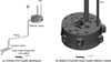 |
Fig. 1 ANSYS fluent model for SSS drain (a) overall CFD model developed, (b) detail of CutCell mesh inside reflector vessel. |
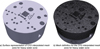 |
Fig. 2 Interpolated unstructured mesh in OpenFoam obtained from CFD code (ANSYS-Fluent). (a) Surface representation of CFD interpolated mesh zone for heavy water zone, (b) mesh definition for the CFD interpolated mesh zone for heavy water zone. |
2.2 Neutronic model
Detailed OPAL neutronic models have been developed using Serpent 2 code, where several comparisons with experimental measurements have been carried out, showing very good agreement for neutron flux profiles, CR worth, and reactivity evolution with burnup for first cycles [4]. Novel capabilities available in Serpent v2.1.28 allows including advanced features such as:
-
Dynamic simulations including delayed neutrons simulation: Dynamic simulation mode [5] has recently included the delayed neutron modelling capability, which allows the simulation of complex subcritical scenarios [6]. As a result, dynamic simulations to model any reactivity insertion can be held without inherent limit to the simulation time (sub, super and prompt super critical).
-
Advanced geometry modelling: Serpent 2 includes the capability to use traditional Monte Carlo approach of constructive solid geometry (CSG − where geometry of the system is composed of homogeneous material cells, defined by intersections, unions and complements of quadratic surfaces) and also advanced geometry based both in unstructured mesh and unstructured surface approach [7]. As a result the capability to embed unstructured mesh geometry from CFD codes is available by the direct-link of OpenFOAM [8] files.
With the aim of these capabilities, the available neutronic models developed in Serpent for OPAL [4] already validated with commissioning measurements were updated to consider:
a) Dynamic behaviour calculations, including rod drop scenario. For such purpose, a series of sources were generated and further used including neutron and precursors distribution.
b) Inclusions of CFD unstructured mesh files from Section 2.1, which were embedded in the available CSG model into the zone representing the reflector zone in the heavy water vessel that surrounds the Reactor core.
c) Modelling of Fission Counter (FC) detectors used in commissioning tests, in the measurement positions.
The resulting geometry is presented in Figure 3, where details for core modelling can be obtained in [4]. It can be observed that the mesh definition includes higher detail where it is required. Besides, the tube positioning for FC 1 to 3 during the commissioning tests are identified.
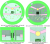 |
Fig. 3 OPAL Serpent 2 model, embedded mesh geometry for reflector vessel − Core centre at x = y = z = 0 cm. (a)x–y cut 3 cm below core centreline − no lines for mesh) − FC positions identified, (b) x–y cut 3 cm below core centreline − mesh detail, (c) x–z cut for y = −15 cm. Detail of axial mesh and position of Fission Counter (yellow), (d) x–y cut 10 cm above core centreline − unstructured mesh detail. |
2.3 Multi-physics coupling
As far as no feedback is required from neutronics to model the heavy water vessel, a one way coupling was performed, where runs for CFD are carried out to feed neutronic models. As a result, the multi-physics coupling was performed just considering the density and material data from each mesh obtained in CFD calculations (and interpolated for the mesh presented in Fig. 2 and Fig. 3) for different drainage times in successive Serpent 2 calculations.
3 Advanced modelling results
Several scenarios were modelled using the thermohydraulic and neutronic models presented in Section 2. The results were compared both with measurements and reactor FSAR values (Final Safety Analysis Report), as presented in the following Sections.
3.1 Rod Drop detector analysis
As far as SSS actuation in OPAL reactor triggers FSS, a first Rod-drop analysis must be performed, without considering CFD coupling. As a result, the neutronic model of Section 2.2 was used to model the Rod-drop test performed during OPAL reactor commissioning. For such purpose the original critical CR configuration was used to build a neutron and precursor written source, which was used afterwards as initial source in transient calculations.
This transient calculation considered a Rod drop behaviour of initial constant velocity and further deceleration to model the OPAL FSS characteristics (preserving the total CR drop time), as shown in Figure 4 for a fully withdrawn CR.
The time results obtained for FC 1 to 3 during the Rod-drop were obtained and compared with measurements from commissioning tests, as shown in Figure 5a. In addition a detailed plot for the first second results is presented in Figure 5b, including the detailed time bin considered in Serpent 2 model. It should be considered that for times below 1 s a 50 ms step was considered, while higher times required integral measurements (of 1 s) due to low count rates in detector measurements.
As it can be seen, a very good agreement between experimental data and Serpent 2 model results is observed for FC-1 to FC-3 both for the initial second (where the original neutron population is more relevant) and for the long-time, where precursors become important.
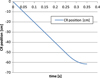 |
Fig. 4 Serpent 2 CR drop considered for a fully withdrawn CR. |
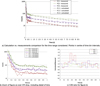 |
Fig. 5 Serpent 2 CR drop detector time results comparison with measured data. (a) Calculation vs. measurements comparison for the time range considered. Points in centre of time bin intervals, (b) Zoom of (a) over CR drop, including detail of bins, (c) C/M ratio for (b). |
3.2 SSS Reactivity Worth calculations
Results from CFD (namely density and materials data) where incorporated in Serpent 2 model for successive times of the CFD transient simulations, as shown in Figure 6 for a couple of time steps. With these drainage profiles successive critical calculations where performed, maintaining the initial CR critical position in order to obtain the SSS worth.
With the reactivity obtained from Serpent 2 model the SSS worth was calculated and compared with available results from FSAR, as presented in Figure 7. It should be noted that the design requirement for SSS is to introduce at least 3000 pcm of negative reactivity in less than 15 s.
As it can be seen, the obtained results of SSS worth obtained with Serpent 2 considering the CFD drain calculations shows a good agreement with results from FSAR. Besides, it can be observed that the design requirement regarding at least 3000 pcm of negative reactivity in less than 15 s is satisfied.
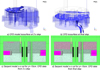 |
Fig. 6 CFD results and Serpent 2 model embedded data into unstructured mesh geometry for reflector vessel − core centre at x = y = z = 0 cm, isosurface at density ∼0.001 g/cm3. (a) CFD model isosurface at 2 s step, (b) CFD isosurface at final step, (c) Serpent model x–z cut for y = −15cm. CFD data from 2 s step, (d) Serpent model x–z cut for y = −15cm. CFD data from final step. |
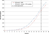 |
Fig. 7 Serpent 2–CFD coupling SSS worth result comparison with FSAR. |
3.3 SSS actuation Multi-physics analysis
Finally, the results from CFD where incorporated in Serpent 2 model for a transient calculation that represents the SSS actuation scenario.
As far as the OPAL design triggers the FSS (i.e. CR drop) when the SSS is demanded, this scenario considered for modelling purposes consisted in two stages, namely:
-
A first rod drop as for Section 3.1, where the reflector vessel is still full of heavy water. To represent such condition, a source that considers neutrons and precursors was saved after the rod drop for further calculation.
-
A series of successive steps of heavy water reflector drain profiles, using the materials and density distributions from Section 3.2. For such purpose a series of successive neutron sources that considers neutrons and precursors were saved after each step (and used in the following step).
The results from Serpent 2 model for the FC-1 to FC-3 where obtained and compared with measurements from SSS actuation tests developed during OPAL commissioning, as shown in Figure 8a. For completeness, the results for the first second (where the CR drop is modelled) and the C/M ratio are also presented in Figure 8b and Figure 8c respectively.
As it can be seen, the obtained results show a very good agreement with experimental data for FC-1 to FC-3 for the first ∼4/5 s. For higher times a slight drift is observed, mainly for FC-2 and FC-3. This deviation is possibly due to slight differences in the drainage profiles from CFD model, which requires further investigation.
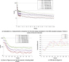 |
Fig. 8 Serpent 2 detector time results with one-through CFD coupling. Comparison with measured data for the SSS scenario. (a) Calculation vs. measurements comparison for the time range considered in the SSS actuation analysis. Points in centre of time bin intervals, (b) Zoom of figure (a) over the first second, including detail of bins, (c) C/M ratio for (b). |
4 Conclusions
The increase of available computer resources, together with the availability of state of art codes both in neutronic and thermo-hydraulic fields allows nowadays developing advanced modelling scenarios for Research Reactors where specific details and behaviour can be simulated. INVAP, as Research Reactor designer develops a continuous improvement program that incorporates state of art techniques and methods in both fields.
In this work series of advanced models for neutronics and thermohydraulic behaviour of key aspects of OPAL Research Reactor were developed. Advanced scenarios that consider both coupled and non-coupled neutronic-thermohydraulic calculation schemes were presented.
The results obtained for FSS (i.e. Rod-Drop) and SSS (i.e. reflector drainage) scenarios measured during OPAL commissioning were calculated and compared with FSAR values and experimental data.
The global comparison shows a very good agreement when comparing calculation results with experimental data, showing the capabilities to develop and manage advanced modelling that allows predicting multi-physics variables observed when an in-depth performance analysis of a Research Reactor like OPAL is carried out.
Further work is intended to be developed in order to perform an in-depth validation of CFD models with experimental data, which will allow developing long-time calculations for the scenarios presented in this work.
Acknowledgments
Authors from this work want to give their special thanks to George Braoudakis (ANSTO, Australia), and to Ville Valtavirta and Jaakko Leppänen (VTT, Finland) who provided key expertise to solve related issues of this work.
References
- International Atomic Energy Agency Report Series No. 480-Research Reactor Benchmarking Database: Facility Specification and Experimental Data − STI/DOC/010/480 (ISBN: 978-92-0-151714-2) − Vienna, 2015 [Google Scholar]
- J. Leppänen, M. Pusa, T. Viitanen, V. Valtavirta, T. Kaltiaisenaho, The serpent Monte Carlo code: status, development and applications in 2013, Ann. Nucl. Energy 82, 142 (2015) [Google Scholar]
- P. Alberto, I. Garnero, Validación de Modelo CFD Multifásico de drenaje del Tanque de Reflector del Reactor OPAL (Multi-phase CFD model validation for Reflector Vessel drainage in OPAL Reactor) − ENIEF 2016 [Google Scholar]
- D. Ferraro, E. Villarino, Full 3-D core calculations with refueling for the OPAL Research Reactor using Monte Carlo Code Serpent 2, Ann. Nucl. Energy 92, 369 (2016) [CrossRef] [Google Scholar]
- J. Leppänen, Development of a Dynamic Simulation Mode in the Serpent 2 Monte Carlo Code. in: M&C 2013, Sun Valley, May 5–9, 2013 (2013) [Google Scholar]
- V. Valtavirta, M. Hessan, J. Leppänen, Delayed Neutron Emission Model for Time Dependent Simulations with the Serpent 2 Monte Carlo Code − First Results. in: PHYSOR 2016, Sun Valley (2016) [Google Scholar]
- J. Leppänen, M. Aufiero, Development of an unstructured mesh based geometry model in the Serpent 2 Monte Carlo Code PHYSOR 2014 (2014) [Google Scholar]
- OpenFOAM User Guide, http://www.openfoam.org/docs/user [Google Scholar]
Cite this article as: Diego Ferraro, Patricio Alberto, Eduardo Villarino, Alicia Doval, A multi-physics analysis for the actuation of the SSS in opal reactor, EPJ Nuclear Sci. Technol. 4, 8 (2018)
All Figures
|
Fig. 1 ANSYS fluent model for SSS drain (a) overall CFD model developed, (b) detail of CutCell mesh inside reflector vessel. |
| In the text | |
|
Fig. 2 Interpolated unstructured mesh in OpenFoam obtained from CFD code (ANSYS-Fluent). (a) Surface representation of CFD interpolated mesh zone for heavy water zone, (b) mesh definition for the CFD interpolated mesh zone for heavy water zone. |
| In the text | |
|
Fig. 3 OPAL Serpent 2 model, embedded mesh geometry for reflector vessel − Core centre at x = y = z = 0 cm. (a)x–y cut 3 cm below core centreline − no lines for mesh) − FC positions identified, (b) x–y cut 3 cm below core centreline − mesh detail, (c) x–z cut for y = −15 cm. Detail of axial mesh and position of Fission Counter (yellow), (d) x–y cut 10 cm above core centreline − unstructured mesh detail. |
| In the text | |
|
Fig. 4 Serpent 2 CR drop considered for a fully withdrawn CR. |
| In the text | |
|
Fig. 5 Serpent 2 CR drop detector time results comparison with measured data. (a) Calculation vs. measurements comparison for the time range considered. Points in centre of time bin intervals, (b) Zoom of (a) over CR drop, including detail of bins, (c) C/M ratio for (b). |
| In the text | |
|
Fig. 6 CFD results and Serpent 2 model embedded data into unstructured mesh geometry for reflector vessel − core centre at x = y = z = 0 cm, isosurface at density ∼0.001 g/cm3. (a) CFD model isosurface at 2 s step, (b) CFD isosurface at final step, (c) Serpent model x–z cut for y = −15cm. CFD data from 2 s step, (d) Serpent model x–z cut for y = −15cm. CFD data from final step. |
| In the text | |
|
Fig. 7 Serpent 2–CFD coupling SSS worth result comparison with FSAR. |
| In the text | |
|
Fig. 8 Serpent 2 detector time results with one-through CFD coupling. Comparison with measured data for the SSS scenario. (a) Calculation vs. measurements comparison for the time range considered in the SSS actuation analysis. Points in centre of time bin intervals, (b) Zoom of figure (a) over the first second, including detail of bins, (c) C/M ratio for (b). |
| In the text | |
Current usage metrics show cumulative count of Article Views (full-text article views including HTML views, PDF and ePub downloads, according to the available data) and Abstracts Views on Vision4Press platform.
Data correspond to usage on the plateform after 2015. The current usage metrics is available 48-96 hours after online publication and is updated daily on week days.
Initial download of the metrics may take a while.