| Issue |
EPJ Nuclear Sci. Technol.
Volume 3, 2017
|
|
|---|---|---|
| Article Number | 26 | |
| Number of page(s) | 12 | |
| DOI | https://doi.org/10.1051/epjn/2017018 | |
| Published online | 12 September 2017 | |
https://doi.org/10.1051/epjn/2017018
Regular Article
Formalization of the kinetics for autocatalytic dissolutions. Focus on the dissolution of uranium dioxide in nitric medium
1
CEA, Nuclear Energy Division, Research Department of Mining and Fuel Recycling Processes, Service of Dissolution and Separation Processes, Laboratory of Dissolution Studies,
30207
Bagnols-sur-Cèze, France
2
CEA, Nuclear Energy Division, Research Department of Mining and Fuel Recycling Processes, SA2I, Laboratory of Chemical Engineering and Instrumentation,
30207
Bagnols-sur-Cèze, France
3
Laboratory of Reaction and Process Engineering, UMR7274, CNRS, Université De Lorraine,
54001
Nancy, France
* e-mail: This email address is being protected from spambots. You need JavaScript enabled to view it.
Received:
1
February
2017
Received in final form:
5
July
2017
Accepted:
17
July
2017
Published online: 12 September 2017
Abstract
Uranium dioxide dissolution in nitric acid is a complex reaction. On the one hand, the dissolution produces nitrous oxides (NOX), which makes it a triphasic reaction. On the other hand, one of the products accelerates the kinetic rate; the reaction is hence called autocatalytic. The kinetics for these kinds of reactions need to be formalized in order to optimize and design innovative dissolution reactors. In this work, the kinetics rates have been measured by optical microscopy using a single particle approach. The advantages of this analytical technique are an easier management of species transport in solution and a precise following of the dissolution rate. The global rate is well described by a mechanism considering two steps: a non-catalyzed reaction, where the catalyst concentration has no influence on the dissolution rate, and a catalyzed reaction. The mass transfer rate of the catalyst was quantified in order to discriminate when the reaction was influenced by catalyst accumulated in the boundary layer or uncatalyzed. This first approximation described well the sigmoid dissolution curve profile. Moreover, experiments showed that solutions filled with catalyst proved to lose reactivity over time. Results pointed out that the higher the liquid-gas exchanges, the faster the kinetic rate decreases with time. Thus, it was demonstrated, for the first time, that there is a link between catalyst and nitrous oxides. The outcome of this study leads to new ways for improving the design of dissolvers. Gas-liquid exchanges are indeed a lever to impact dissolution rates. Temperature and catalyst concentration can be optimized to reduce residence times in dissolvers.
© F. Charlier et al., published by EDP Sciences, 2017
 This is an Open Access article distributed under the terms of the Creative Commons Attribution License (http://creativecommons.org/licenses/by/4.0), which permits unrestricted use, distribution, and reproduction in any medium, provided the original work is properly cited.
1 Introduction
Reprocessing of spent nuclear fuel is based on liquid–liquid extraction of dissolved species. Dissolution of nuclides is hence at the head end of the reprocessing process and impacts all the following steps. This study concentrates on uranium dioxide dissolution as it represents 96% of spent fuel [1].
However, micro-scale phenomena controlling dissolution are complex and mainly unknown. The coupled physics and chemistries involved in dissolution reactions are still unclear although a better understanding could lead to faster processes and less energy and solvent consuming dissolvers.
The first step in designing a model for a dissolution reactor is to formalize the mechanism and chemical kinetic of the reaction.
1.1 Nitric medium complexity
UO2 reaction in nitric acid is particularly complex. First of all, reactions in nitric medium are numerous as HNO3 is a powerful acid but also oxidant. Sicsic et al. [2], Schwartz and White [3,4] gave an overview of the numerous equilibrium, and their thermodynamics, linked to nitric acid. The species that need to be considered in order to describe the nitric medium [2] are reported in Table 1. The physical state and known stability are given for standard conditions.
Dissolution products are uranyl nitrates. There are mainly four complexes in nitric medium:  ,
,  ,
,  , and
, and  , whose prevalence depends on nitric acid concentrations [5]. In our conditions, with 2–7 mol·l−1 of nitric acid,
  is the main species [5].
The reaction is triphasic and produces also nitric oxides NOX which may modify the equilibrated reactions in the nitric solution [6].
This diversity of species explains why many different hypotheses can be found in literature about the mechanism of UO2 dissolution.
1.2 Dissolution mechanism
Fournier summarized this complexity in her thesis with a list of all the balanced equations considered in literature [7].
Mainly three hypotheses about the mechanism can be highlighted, which explain the presence of the most stable species: HNO3, HNO2, NO2, N2O4 and NO. N2O does not appear here as it was proven to be a parallel product by Marc [8].  presence can be explained by nitric acid dissociation.
The first hypothesis was described by Shabbir and Robbins [9] who suggested two simultaneous reactions depending on nitric acid concentration (1).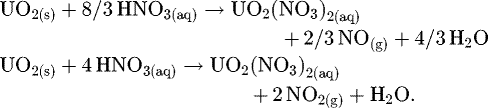 (1)
(1)
The second hypothesis was defined by Sakurai [6], who suggested that NO is the only dissolution product and that NO2 is observed because of the equilibrium presented at equation (2). K is the thermodynamic constant of the reaction.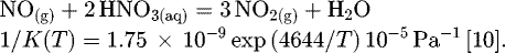 (2)
(2)
Lefers and Sicsic [2,10] also mentioned equilibrium (3) for low acidities. As NO(aq) free enthalpy does not exist in literature, the thermodynamic constant cannot be calculated here [2]. (3)
(3)
The last hypothesis proposed by Ikeda considers HNO2 as an intermediary and is detailed in equation (4).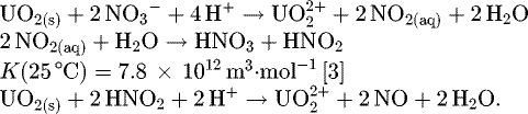 (4)
(4)
Actually NO2 is also in fast equilibrium with N2O4 [3], which is far more soluble, so it should most probably be the species to be considered in the second step in equation (4) instead of NO2. Moreover, this step is very fast and led to the global expression (5)[7].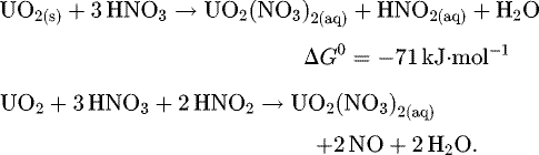 (5)
(5)
1.3 An autocatalytic reaction
Marc [8] proved recently that UO2 dissolution is definitely an autocatalytic reaction, which means one of its products accelerates its kinetic rate.
Ikeda and Marc include the autocatalytic aspect by defining a two-step mechanism [8,11]. First, a slow non-catalytic reaction is observed where the catalyst is produced (HNO2 for Ikeda), and after some time, a second faster parallel catalytic reaction proceeds, where the catalyst accelerates the dissolution rate.
This was described by Marc [8] as shown in equation (6). Due to aforementioned complex reactions in nitric medium, the catalyst species for UO2 dissolution is still unknown. Although HNO2 is frequently cited [7], the catalyst can be the result of side reactions or an unstable byproduct. Catalyst is thus referred as ‘Z’ in this article. (6)
(6)
The global chemical kinetic rate for this mechanism can be expressed by equation (7). The kinetic constants knc and kc are defined by Arrhenius expressions.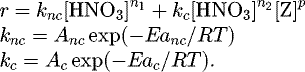 (7)
(7)
This mechanism enables to include the autocatalytic aspect of the reaction but may need the addition of parallel equilibria mentioned above to describe entirely the global reaction.
1.4 Diffusion rate
Determination of the kinetic parameters is tricky. Indeed, for heterogeneous reactions, a delicate point for the kinetic study is that the global kinetic rate of UO2 dissolution is determined not only by reaction kinetics, but also physical kinetics, linked, among other factors, to the transport of species. If such transport phenomena are slow compared to the chemical kinetic rate, the concentrations at the solid/liquid interface might be different from those measured in the bulk.
To simplify, if diffusion of species is not a rate-determining step, the reaction is said to be under chemical reaction control. Otherwise, the concentrations of species at the solid surface are different from their concentrations in the bulk. The reaction is under diffusion control.
The external diffusion flux density was defined by equation (8).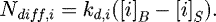 (8)
(8)
A material balance applied to the boundary layer of UO2 particles led to equation (9). The apparent dissolution rate, rapp, depends on the particle surface concentrations, which are not experimentally measurable. The thickness of the boundary layer δ has the same order of magnitude as the particle size.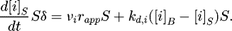 (9)
(9)
The diffusion and reaction flux reach equilibrium quickly. Equation (9) was considered at this equilibrium and the accumulation term is hence negligible compared to the diffusion and reaction rates.
kd,i was defined according to Sherwood number for a single particle and low flowrates (Re ≤ 800) [12], the relation is given at equation (10).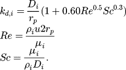 (10)
(10)
1.5 External resistance fraction for the nitric acid
According to these hypotheses and equation (9), an external resistance fraction is defined [13]. For nitric acid, its expression is presented at equation (11).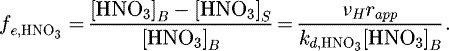 (11)
(11)
Kinetic rates depend on nitric acid concentrations with the order n1 for the non-catalyzed reaction. The concentration difference between the surface and the bulk was considered negligible when kinetics were impacted at less than 5 percent, as put with equation (12). The kinetics of the reaction at the solid surface are  , and
, and  are the kinetics if the bulk concentration were considered.
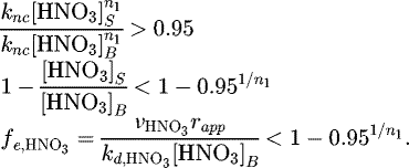 (12)
(12)
In literature, n1 is mostly in the range of 2–4 [7]. Relations (12) show that with the maximum value 4, the external diffusion fraction for the nitric acid should be lower than 1.3% to ensure that the reaction is under chemical control.
1.6 External resistance fraction for the catalyst
The external resistance fraction for the catalyst is defined by equation (13) (13)
(13)
The kinetics at the interface and in the bulk are considered identical if the difference between them is less than 5%. This means equation (14) must be respected.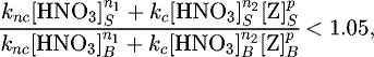 (14)ω is defined as the ratio of kc over knc at equation (15).
 (15)
(15)
If nitric acid concentrations in the bulk and at the solid surface were the same, and considering that n1 ≈ n2 and p ≥ 1, the external resistance fraction for the catalyst must then obey equation (16).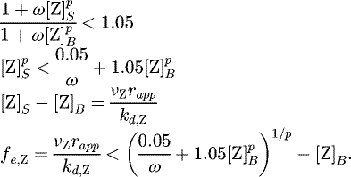 (16)
(16)
In this case, the dissolution rates at time t and t0 are compared. Furthermore, in the absence of catalyst in the bulk, there is no influence of the catalyst on the dissolution kinetics if equation (17) is respected.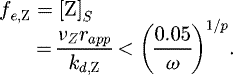 (17)
(17)
According to the results published by Ikeda et al. [11], knc = 5.0 × 10⁻⁷ mol1−2.3·m−2+3·2.3·s−1 and knc = 8.5 × 10⁻⁸ mol2.3·m−2+3·2.3+3·s−1 at 50 °C. With these values, ω = 0.17 m3·mol−1. Moreover, the order relative to the catalyst always equals 1 in the publications where a catalyst is considered [11,14]. In the event of a dissolution with no catalyst in the bulk, fe,Z must be lower than 0.29 mol·m−3 to avoid any impact of the catalyst in the boundary layer.
1.7 Accumulation of species in the bulk
The concentration of species in the bulk must also be constant during the entire dissolution. To respect this condition, the solid quantity must be negligible compared to nitric acid. Factor X was defined by equation (18) to compare the molar quantity of nitric acid consumed by UO2.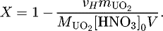 (18)
(18)
If X is close to 1, the impact of the dissolved solid on the bulk concentrations is considered inconsequential.
1.8 Kinetic study
To formalize the reaction kinetics, the influence of temperature, nitric acid and catalyst concentrations must be quantified. Reaction orders relative to nitric acid and activation energies have been extensively studied by authors [8,9,11,15–17]. Part of the literature data is summarized in Tables 2 and 3. The external resistance factor for nitric acid, and the solid/liquid ratio X, are also calculated according to experimental conditions published by the authors.
However, few of them discriminated the catalyzed and non-catalyzed reactions. Since, the aim of this work is to formalize the reaction kinetics by considering both reactions, the factors defined previously are used to discriminate the rate determining step for experimental data. Moreover, ratio X is used to quantify the catalyst quantity in the bulk.
These results will be helpful for further modeling of the global kinetics, including the influence of mass transfer. Indeed, in the special case of an autocatalytic reaction, mass transfer can have a positive impact on the dissolution rate because of catalyst build-up at the solid surface. Marc [8] already showed that catalyst accumulates better in pits of the solid than at the surface, which explains why preferential attack sites are observed during UO2 dissolution [18].
Another important aspect is that the reaction is triphasic. Taylor et al. [15] highlighted that dissolution rates at temperatures near boiling are lower than the one expected with Arrhenius law. Ikeda et al. [11] explained this observation by an unstable catalyst, whose decomposition is faster at high temperatures. Nishimura et al. [14] also showed a decrease in temperature dependence for a dissolution rate above 80 °C. Their explanation is that catalyst is unstable and decomposes into gas. The current work also focuses on the link between gas and catalyst and proposes to include the catalyst decomposition in the chemical kinetic rate.
Orders n relative to nitric acid, proton or nitrate in literature.
Activation energies in literature.
2 Experimental set up
2.1 Reagents
Uranium dioxide powder was provided by the CETAMA of CEA Marcoule. Mass spectrometry shows that impurity values are less than 100 ppm. O/U ratio was calculated thanks to X-ray diffraction and is equal to 2.04 ± 0.02. Nitric acid solutions were prepared by dilution of 68% nitric acid AnalaR NORMAPUR (ref. 20422.297). Each diluted solution was titrated by mean of 800 Dosino, fed with 0.1 mol·l−1 sodium hydroxide.
2.2 Kinetic study cell
A kinetic study dissolution cell was defined. The efficient volume of the cell was 5 ml. KD Scientific Legato 270 Push/pull syringe pump of 30 ml enabled to renew the nitric acid at a rate of 1 ml·min−1 when needed. A Peltier thermoelectric heating module, monopuit MW1, designed by Anacrismat company, enabled to maintain the temperature in the cell. A probe also measured the solution temperature and it was verified to be stable during the entire dissolution.
2.3 Measurement of dissolution rate
Acquisitions of the kinetics were made thanks to optical microscopy. The method was developed by Marc [8] and consists in following the projected areas of UO2 particles during dissolution.
Image treatment was done with a homemade software developed on Scilab [23] to extract areas and perimeters of every particles. Dissolution rates r, in m·s−1, were calculated according to equation (19). Several particles were followed in order to have a mean dissolution rate.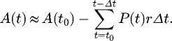 (19)
(19)
To get a value in mol·m−2·s−1, dissolution rates were converted according to equation (20).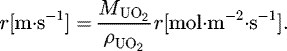 (20)
(20)
This analytical technique enables a very small quantity of solid, less than 1 mg, and a precise in-situ following of the dissolution.
Transmission mode was used which enabled a better contrast. Moreover, the light came from above the sample to avoid any perturbations from nitrogen bubbles produced by the reaction.
2.4 How to study the catalyzed reaction?
The catalytic reaction was studied by dissolving a predefined quantity of UO2 powder in nitric acid. At the end of such a dissolution, the final solution contains a defined quantity of reaction products: uranyl nitrate  but also catalyst. This solution is defined as loaded with catalyst. Figure 1 describes the entire process.
The hypothesis here is that one mole of UO2 gives one mole of catalyst. νZ is hence supposed equal to 1. The ratio X defined previously at equation (18) is also representative of the catalyst and initial acid concentration ratio. Table 4 presents the mass balance as a function of X after dissolution. If X = 1, there is no catalyst in the solution. If X = 0, nitric acid has been totally consumed by the reaction.
The dissolution of fresh UO2 particles was thus followed by microscopy in the solution loaded with catalyst by this method. The catalyzed reaction was studied for different pre-dissolved masses.
Moreover, Delwaulle [24] showed in her work that copper is a good surrogate to study uranium dioxide dissolution. The reaction is similar as it is also autocatalytic and leads to the same gaseous products. We thus compared dissolution rates of UO2 particles with pre-dissolved masses of copper or uranium dioxide. Results are presented in Figure 2. For the same experimental conditions, solutions loaded with the same molar quantity of copper or uranium dioxide gave the same dissolution rate. This means that catalyst is linked to the nitric acid or NOX and not to the solid.
Metal copper was hence sometimes used to load solutions for the following experiments, figure captions indicate the loading species. Copper powder was provided by Merck, reference 1.02703.1000.
To define the influence of the catalyst, solutions were prepared by dissolving 0 to 1.37 g of UO2, or 0–1.78 g of Cu, in 50 ml of 5.3 mol·l−1 nitric acid. The dissolution temperature was 50 °C. Uranyl nitrate or copper nitrate concentrations in the solutions were verified with ICP-AES.
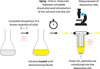 |
Fig. 1 Diagram of the experimental protocol for catalyzed reaction studies. |
Mass balance during the dissolution as a function of X.
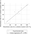 |
Fig. 2 Comparison between dissolution rates for solutions loaded in UO2 or copper. |
2.5 Link between gas and catalyst
If the catalyst were indeed linked with gas production, degassing of the solution could explain that the reactivity is lower than expected at high temperatures. To test this hypothesis, three solutions were prepared, each of them enabling more or less exchange between gas and liquid.
In the first solution, 1.71 g of copper was dissolved in 100 ml of 5.3 mol·l−1 nitric acid in order to obtain solutions where X = 0.85. After complete copper dissolution and at different time intervals, 5 ml of the solution was transferred into the dissolution cell, where measurements on new UO2 particles were done. This elapsed time represents the aging of the solutions. The three samples underwent different treatments:
the first sample was left open. Gas escaped through the top of the flask;
a film of paraffin oil was injected into the second flask. This viscous layer limited the exchange between gas and liquid. Every 5 min, 5 ml of the solution was drawn up in the reactor through a syringe. Valves enabled to close the system between each sampling;
the last flask was also exposed to open air and N2 was bubbled at a rate of 70 ml·min−1 to improve gas liquid exchanges. A 5 ml sample of the solution was injected into the dissolution cell every 10 min.
2.6 Nitrous oxides and dissolution rate
Another experiment was made where 1.37 g of copper was dissolved in 100 ml of 4.8 mol·l−1 nitric acid. Four 10 ml test tubes were completely filled with this solution and closed. The solution in the test tube is called solution A. As for previous experiments, nitrogen was bubbled in the remaining solution, called solution B, for 60 min to ensure the removal of catalyst species. NOX(g), produced by the dissolution of 2.40 g of copper in 50 ml HNO3 in another flask, are then injected into the degassed solution.
The dissolution cell was then alternatively filled with the solution of one closed test tube or with the solution under nitrogen stream. UO2 particles dissolution rates were followed by microscopy.
3 Results and discussion
3.1 Dissolution curve profile
The uranyl nitrate concentrations in the solution after dissolution were measured thanks to ICP-AES and were equal to the ones before dissolution, confirming there is no accumulation of species in the bulk.
The resistance fractions  were calculated according to the apparent dissolution rates with
  chosen according to literature data [12]: 3 × 10⁻⁹ m2·s−1. The external resistance was always lower than 0.01%, which means the nitric acid diffusion rate does not impact the kinetics.
A typical dissolution curve is shown in Figure 3.
The kinetics at each times were approximated by equation (21) and are represented in Figure 4.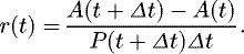 (21)
(21)
It was stated previously that the external resistance fraction for the catalyst must be lower than 0.29 mol·m−3. The maximum dissolution rate rapp,max for which fe,Z reaches this value was calculated according to equation (22). As a first approximation, DZ was considered equal to nitric acid diffusivity. The particle radius rp was taken at the beginning of the dissolution to maximize the resistance fractions.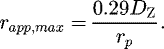 (22)
(22)
The maximum apparent rate rapp,max is represented in Figure 4. The measured dissolution rates above this value were impacted by more than 5% by the catalyst concentration at the solid–liquid interface. This explains the sigmoid profile of dissolution curves: the reaction is non-catalyzed and very slow at the beginning, from 0 to 400 s. After this time, the catalyst accumulates at the solid surface and the reaction rate increases.
The equilibrium between diffusion and reaction flux is reached and the reaction rate is constant between 400 and 500 s. The dissolution rate measured here is representative of the catalyzed reaction. The catalyst concentration at this point can be approximated by equation (23).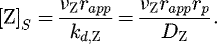 (23)
(23)
However, the catalyst concentration is controlled by mass transfer, and the mass transfer coefficient is increasing as the particle radius is decreasing. This means the concentration of catalyst at the surface is decreasing with particle radius. That is why the dissolution rate diminishes between 500 and 1000 s.
Finally, another range where the dissolution rate is constant is reached. In this case, the apparent dissolution rate is lower than the limit for which the diffusion of catalyst impacts the kinetics. From 1000 s to the end of the dissolution, the apparent dissolution rate is under chemical reaction control. As there is no catalyst in the bulk, this dissolution rate is also the rate the non-catalyzed reaction.
For all the following experiments,  and fe,Z were calculated and enabled to determine whether the dissolution is under chemical control or not. The kinetics were chosen on the range where they do not depend on mass transfer.
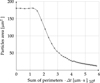 |
Fig. 3 Dissolution curve profile. X = 1, T = 63.2 °C. |
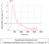 |
Fig. 4 Evolution of dissolution rate. X = 1, T = 63.2 °C. |
3.2 Relative order to nitric acid
The reaction order relative to nitric acid was measured for the catalyzed reaction and was found to be 3.08 ± 0.32 (Fig. 5). This observation is coherent with literature data [7]. The reaction order relative to nitric acid for the non-catalyzed reaction was chosen equal to 3.5 according to Marc's results in a continuous cell and at 50 °C [8].
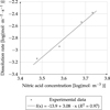 |
Fig. 5 Relative order to nitric acid for the catalyzed reaction. Solutions loaded in copper, T = 50 °C and X = 0.96. |
3.3 Activation energies
Arrhenius graphs for catalyzed and non-catalyzed reactions are presented in Figure 6.
Interestingly, a detailed observation of Figure 6 shows that the activation energies are not completely independent of temperatures. At least two slope changes can be seen for the non-catalyzed data, the first one around 50 °C and the second one at 70 °C. This is coherent with the observations made by Marc [8], who identified four sections of temperature with different activation energies. For the catalyzed reaction a change of slope is also seen around 70 °C.
These phenomena could be explained by a change in nitric medium equilibrium with temperature. For example, Sicsic et al. [2] mentioned that nitric acid dissociation is less favored at high temperature. Taylor suggested that the nitrates, more than the protons, were the important reactants in UO2 dissolution [15]. Hence, with high temperatures, there are lower free nitrate in solution, which could explain the lower dissolution rate observed.
However, this is only one possibility among over. Still, the mean activation energies were calculated within the temperature range [30–70 °C]. Without catalyst, the activation energy was 63.0 ± 3.1 kJ·mol−1. The frequency factor was determined as stated in relation (24) and was equal to 1.6 × 10⁻⁸ mol1–3.5·m3×3.5–2·s−1. (24)
(24)
The activation energy for the catalyzed reaction is higher: 79.1 ± 11.2 kJ·mol−1 at X = 0.80. This seems to be incoherent with the usual definition of a catalyst. However, the product that accelerates the kinetic rate is inaccurately called catalyst as it appears in the equation balance of the dissolution, it must be considered instead as another reactant. Thus, it could not necessarily reduce the activation energy. Nonetheless, the measurement of two different activation energies in the presence or absence of catalyst supports the hypothesis of two different reactions.
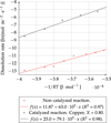 |
Fig. 6 Arrhenius laws for the non-catalyzed and catalyzed reactions. |
3.4 Influence of the catalyst
Figure 7 represents the dissolution rate for UO2 particles in solutions loaded with different mass of UO2 or copper. The ratio X is representative of the pre-dissolved mass. The maximum rate for which the external resistance fraction for nitric acid is equal to 1.3% was calculated for particles with a radius of 15 μm. This limit is represented in black in Figure 7. Particles bigger than this radius were not included in the calculation of the average rate.
The external resistance fraction for the catalyst was calculated for p = 1. There is no gradient of concentrations to consider if equation (25) is respected.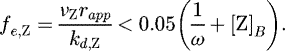 (25)
(25)
The catalyst concentration in the bulk [Z]B is linked to acid consumption during predissolution as defined in (4). This leads to the expression equation (26) for the catalyst concentration.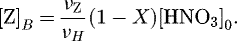 (26)
(26)
The maximum rate respecting this condition is expressed by the linear expression equation (27). This relation is represented in green in Figure 7 for particles whose size equals 8 μm. Smaller particles were thus promoted for the kinetic acquisition. However some experimental data are above the maximum rate value for a 5% tolerance. If the tolerance were increased to 10%, all the experimental data would be under the maximum rate above which the reaction is impacted by mass transfer. We consider for the following experiments that all data were measured under chemical control. (27)
(27)
Experimental points were fitted with the expression of the kinetics defined in Table 5. The kinetic order for nitric acid for the non-catalyzed reaction n1 is fixed to 3.5 and n2 to 3.1. We calculated knc at 50 °C according to previous results to be 8.2 × 10⁻¹⁹ mol1–3.5·m3·3.5–2·s−1. The respective orders relative to catalyst p and kc were then optimized thanks to Levenberg Marquardt algorithm [25]. Table 5 summarizes the results, and the constant kc is expressed in moln2·m1+3 n2·s−1.
The results demonstrate an optimum value for the dissolution rate for a value of X around 0.85 for a nitric acid concentration of 5 mol·l−1.
In any case, we show that former published kinetic parameters must be considered very carefully as they may include several side reactions, diffusion kinetics and accumulation. The parameters proposed here are void of any mass transfer and accumulation. Furthermore, catalyzed and non-catalyzed reactions are discriminated.
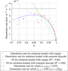 |
Fig. 7 Influence of the load in catalyst on the dissolution rate. |

Kinetic parameters for the catalyzed reaction.
3.5 Nitrous oxide and dissolution rate
The results for the influence of degassing are presented in Figure 8. The dissolution rates for the flask with paraffin, where gas was trapped inside the solution, were clearly higher. The lowest dissolution rates appear for the solution under N2 flowrate, where reactivity of the solution falls to almost zero in less than one hour of aging.
For the second experiment, as before, the reactivity of the solution B where nitrogen was bubbled fell in less than one hour to almost zero. But, when NOX was bubbled again in the same solution, it regained very quickly its initial reactivity. The dissolution rate is then the same as the one observed at the beginning of the experiment (Fig. 9).
With solution A aged in closed test tubes the dissolution rate is almost constant and only slightly decreases for the last test tubes. This can be explained by the loss of gas when the tubes were opened when filling the dissolution cell.
Thus, we demonstrated, for the first time, that dissolution rates are linked to degassing of solutions. The best explanation for this phenomenon is that the catalyst is closely linked to nitrous oxides. The increase of reactivity obtained when NOX is trapped in the solution shows that kinetics can be optimized by acting on nitrous oxide concentrations in the solution and the gas phase.
These observations could explain why Taylor et al. [15] and Shabbir et al. [9] noticed a change of Arrhenius plot slope when temperatures are close to boiling. Indeed, solubility of gas is lower at high temperature, and therefore the observed reaction may near the non-catalyzed reaction.
The results strengthen the conclusions of Nishimura et al. [14] and Fukasawa [26] about a relationship between catalyst and gas. In their work HNO2 is considered as the catalyst and it is linked to gas thanks to the decomposition reaction (28). (28)
(28)
However, Schwartz and White [4] and Park and Lee [26] showed that the reverse reaction is faster. Moreover, Marc also argued that such a slow reaction could hardly lead to concentrations of gas high enough to nucleate bubbles [8].
Another reaction that links NOX and HNO2 is the absorption reaction of N2O4 presented at equation (29) [3,10,11].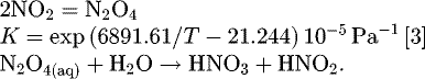 (29)
(29)
However, there is no proof yet that these reactions are the one impacting the dissolution rates. Two different scenarios must be considered:
the dissolution produces gases. In turn, these gases generate the catalyst;
the dissolution produces the catalyst, the catalyst is unstable and leads to gas production.
Moreover, the reaction between gas and catalyst may not reach the equilibrium. Its own kinetics should then be included in the global mechanism in order to determinate the dissolution rate.
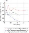 |
Fig. 8 Influence of degassing on dissolution rate. Solutions loaded with copper. |
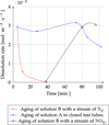 |
Fig. 9 Influence of nitrous oxide on dissolution rate. solutions loaded with copper. |

4 Conclusion
The global kinetic for autocatalytic dissolutions is not easy to formalize as it includes not only chemical phenomenon but also physical phenomenon. The following elements must be taken into account:
Autocatalysis. In-situ optical microscopy enabled us to discriminate two steps of the chemical dissolution reaction. The separated study of catalyzed and non-catalyzed reaction led to expression (30) for the UO2 chemical dissolution rate in mol·m−2·s−1.
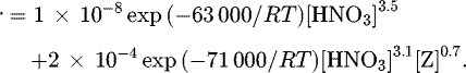 (30)
(30)Mass transfer. Resistance factors were defined for both the catalyst and nitric acid in order to discriminate whether the kinetic rate is under chemical or diffusion control. Mass transfer has a great impact on dissolution rate as only a small quantity of catalyst in the boundary layer can boost the dissolution.
Link between catalyst and nitric oxides. Experiment showed there must be a reaction between the catalyst and nitric oxide. Although this reaction is still unknown, it needs to be characterized to be included in the global kinetic rate.
Gas-liquid exchanges. They are a mean to influence the catalyst concentration in the solution. They must definitely be taken into account for the global dissolution rate of reactors with high mass transfer rates between gas and liquid.
All these elements play an important part on the global dissolution rate. Characteristic phenomenon times must be defined for each of them and should systematically be calculated for a specific reactor in order to estimate whether they really impact UO2 dissolution.
Nomenclature
[i]: concentration of species i in mol·m−3
[i]B: concentration of species i in the bulk in mol·m−3
[i]S: concentration of species i at the solid surface in mol·m−3
A(t): area of the particles at time t in m2
Anc: frequency factor for the non-catalyzed reaction in mol1−n1·m3·n1−2·s−1
Ac: frequency factor for the catalyzed reaction in mol1−n2−p·m3·n1+p−2·s−1
Di: diffusivity of species i in m2·s−1
Eanc: activation energy for the non-catalyzed reaction in kJ·mol−1
Eac: activation energy for the catalyzed reaction in kJ·mol−1
ΔG0: standard Gibbs free energy in kJ·mol−1
 : initial nitric acid concentration in mol·m−3
kd,i: mass transfer coefficient in m·s−1
K: thermodynamic constant
knc: kinetic constant for the non-catalyzed reaction in mol1−n1·m3·n1−2·s−1
kc: kinetic constant for the catalyzed reaction in mol1−n2−p·m3·(n1+p)−2·s−1
 : UO2 mass in kg
 : molar mass of UO2 in kg·mol−1
n1: order relative to acid concentration for the non-catalyzed reaction
n2: order relative to acid concentration for the catalyzed reaction
Ndiff,i: external diffusion flux density for species i in mol·s−1·m−2
P(t): perimeter of the particles at time t in m
p: order relative to catalyst concentration for the dissolution reaction
r: chemical dissolution rate in mol·m−2·s−1
R: perfect gas constant in J·mol−1·K−1
rapp: apparent dissolution rate in mol·m−2·s−1
rp: particle radius in m
Re: Reynolds adimensional number
S: area of solid surface in m2
Sc: Schmidt adimensional number
T: temperature in K
u: velocity of the fluid in m·s−1
V: nitric acid volume in m3
μi: cinematic viscosity m2·s−1
δ: thickness of the boundary layer in m
νH: stoichiometric coefficient for nitric acid
νZ: stoichiometric coefficient for the catalyst
ω: ratio between the catalyzed and non-catalyzed kinetic constant
 : density of UO2 in kg·m−3
Acknowledgments
This work was financed by the French Alternative Energies and Atomic Energy Commission. The authors are thankful to the Laboratory of material and chemical analysis (LMAC) of CEA Marcoule for the characterization of the UO2 powder. Many thanks also to the laboratory of chemical engineering and instrumentation (LGCI) and to Laure Clavel and Abdelhalim Achahbouni from CEA, laboratory of advanced technologies of nuclear cycle process (LTAP), for their contribution to experimentations.
References
- Treatment and recycling of spent nuclear fuel. Actinide partitioning − application to waste management, edited by J.M. Parisot (Editions le Moniteur, Paris 2008) [Google Scholar]
- D. Sicsic, F. Balbaud-Celerier, B. Tribollet, Mechanism of nitric acid reduction and kinetic modelling, Eur. J. Inorg. Chem. 2014, 6174 (2014) [CrossRef] [Google Scholar]
- S.E. Schwartz, W.H. White, Solubility equilibria of the nitrogen oxides and oxyacids in dilute aqueous solution, Adv. Environ. Sci. Eng. 4, 1 (1981) [Google Scholar]
- S.E. Schwartz, W.H. White, Kinetic of reactive dissolution of nitrogen oxides into aqueous solution, Adv. Environ. Sci. Technol. 12, 1 (1983) [Google Scholar]
- Y. Ikeda, C. Hennig, S. Tsushima, A.C. Scheinost, G. Bernhard, T. Yaita, Speciation and structural study of U(IV) and −(VI) in perchloric and nitric acid solutions, Inorg. Chem. 48, 7201 (2009) [CrossRef] [Google Scholar]
- T. Sakurai, A. Takahashi, N. Ishikawa, Y. Komaki, The composition of NOX generated in the dissolution of uranium dioxide, Nucl. Technol. 83, 24 (1988) [CrossRef] [Google Scholar]
- S. Fournier, Étude de la dissolution des oxydes mixtes (U,Pu)O2 à forte teneur en plutonium, PhD thesis, Université de Montpellier II, November 2000 [Google Scholar]
- P. Marc, Étude de réactions hétérogènes autocatalytiques. Application à la dissolution du dioxyde d'uranium, PhD thesis, Université de Lorraine, December 2014 [Google Scholar]
- M. Shabbir, R.G. Robins, Kinetics of the dissolution of uranium dioxide in nitric acid. I, J. Appl. Chem. 18, 129 (1968) [CrossRef] [Google Scholar]
- J.B. Lefers, Absorption of nitrogen oxides into diluted and concentrated nitric acid, PhD thesis, Delft University, 1890 [Google Scholar]
- Y. Ikeda, Y. Yasuike, K. Nishimura, S. Hasegawa, Y. Takashima, Kinetic study on dissolution of UO2 powders in nitric acid, J. Nucl. Mater. 224, 266 (1995) [CrossRef] [Google Scholar]
- D.W. Green, J.O. Maloney, R.H. Perry, Perry's chemical engineers' handbook (McGraw-Hill, New York, London 1998) [Google Scholar]
- J. Villermaux, Génie de la réaction chimique. Conception et fonctionnement des réacteurs (Éditions Tec & Doc, Paris 1963) [Google Scholar]
- K. Nishimura, T. Chikazawa, S. Hasegawa, H. Tanaka, Effect of nitrous acid on dissolution of UO2 powders in nitric acid. Optimal conditions for dissolving UO2, J. Nuclear Sci. Technol. 32, 157 (1995) [CrossRef] [Google Scholar]
- R.F. Taylor, E.W. Sharratt, L.E.M. De Chazal, D.H. Logsdail, Dissolution rates of uranium dioxide sintered pellets in nitric acid systems, J. Appl. Chem. 13, 32 (1963) [CrossRef] [Google Scholar]
- Y. Zhao, J. Chen, Studies on the dissolution kinetics of ceramic uranium dioxide particles in nitric acid by microwave heating, J. Nucl. Mater. 373, 53 (2008) [CrossRef] [Google Scholar]
- L. Clapadere, F. Tocino, S. Szenknect, A. Mesabbah, N. Clavier, P. Moisy, N. Dacheux, Dissolution of Th1−xUxO2: effects of chemical composition and microstructure, J. Nucl. Mater. 457, 304 (2015) [CrossRef] [Google Scholar]
- A.L. Uriarte, R.H. Rainey, Dissolution of high-density UO2, PuO2, and UO2–PuO2 pellets in inorganic acids, ORNL technical document, April 1963 [Google Scholar]
- A. Leudet, A. Mugnier, Etude de la cinétique de dissolution des pastilles d'UO2 non irradiées, Document technique DEN, June 1985 [Google Scholar]
- B. Herrmann, Dissolution de pastilles d'UO2 non irradiées dans de l'acide nitrique, Projet de retraitement et de traitement des déchets, 1984 [Google Scholar]
- Y. Zhao, J. Chen, Comparative studies on the dissolution of ceramic UO2 pellets in nitric acid by microwave and conventional heating, Radiochim. Acta 96, 467 (2008) [CrossRef] [Google Scholar]
- Y. Zhao, J. Chen, Kinetics study on the dissolution of UO2 particles by microwave and conventional heating in 4 mol·L−1 nitric acid, Sci. China Ser. B: Chem. 51, 700 (2008) [Google Scholar]
- Scilab Enterprises, Scilab: free and open source software for numerical computation (Scilab Enterprises, Orsay, France, 2012) [Google Scholar]
- C. Delwaulle, Étude de la dissolution du dioxyde d'uranium en milieu nitrique : une nouvelle approche visant à la compréhension des mécanismes interfaciaux, PhD thesis, Institut National Polytechnique de Lorraine, November 2011 [Google Scholar]
- D. Marquardt, An algorithm for least-squares estimation of nonlinear parameters, J. Soc. Ind. Appl. Math. 11, 431 (1963) [Google Scholar]
- T. Fukasawa, Y. Ozawa, F. Kawamura, Generation and decomposition behavior of nitrous acid during dissolution of UO2 pellets by nitric acid, J. Nucl. Technol. 91, 108 (1991) [CrossRef] [Google Scholar]
- J.Y. Park, Y.N. Lee, Solubility and decomposition kinetics of nitrous acid in aqueous solution, J. Phys. Chem. 92, 6294 (1988) [CrossRef] [Google Scholar]
Cite this article as: Florence Charlier, Delphine Canion, Anthony Gravinese, Alastair Magnaldo, Sophie Lalleman, Gilles Borda, Éric Schaer, Formalization of the kinetics for autocatalytic dissolutions. Focus on the dissolution of uranium dioxide in nitric medium, EPJ Nuclear Sci. Technol. 3, 26 (2017)
All Tables
All Figures
|
Fig. 1 Diagram of the experimental protocol for catalyzed reaction studies. |
| In the text | |
|
Fig. 2 Comparison between dissolution rates for solutions loaded in UO2 or copper. |
| In the text | |
|
Fig. 3 Dissolution curve profile. X = 1, T = 63.2 °C. |
| In the text | |
|
Fig. 4 Evolution of dissolution rate. X = 1, T = 63.2 °C. |
| In the text | |
|
Fig. 5 Relative order to nitric acid for the catalyzed reaction. Solutions loaded in copper, T = 50 °C and X = 0.96. |
| In the text | |
|
Fig. 6 Arrhenius laws for the non-catalyzed and catalyzed reactions. |
| In the text | |
|
Fig. 7 Influence of the load in catalyst on the dissolution rate. |
| In the text | |
|
Fig. 8 Influence of degassing on dissolution rate. Solutions loaded with copper. |
| In the text | |
|
Fig. 9 Influence of nitrous oxide on dissolution rate. solutions loaded with copper. |
| In the text | |
Current usage metrics show cumulative count of Article Views (full-text article views including HTML views, PDF and ePub downloads, according to the available data) and Abstracts Views on Vision4Press platform.
Data correspond to usage on the plateform after 2015. The current usage metrics is available 48-96 hours after online publication and is updated daily on week days.
Initial download of the metrics may take a while.