| Issue |
EPJ Nuclear Sci. Technol.
Volume 11, 2025
Status and advances of Monte Carlo codes for particle transport simulation
|
|
|---|---|---|
| Article Number | 2 | |
| Number of page(s) | 5 | |
| DOI | https://doi.org/10.1051/epjn/2024017 | |
| Published online | 08 January 2025 | |
https://doi.org/10.1051/epjn/2024017
Regular Article
COG 11.3 New Features
Lawrence Livermore National Laboratory, 7000 East Avenue, L-198, Livermore, CA, 94550, USA
* e-mail: This email address is being protected from spambots. You need JavaScript enabled to view it.
Received:
16
June
2024
Received in final form:
18
September
2024
Accepted:
3
October
2024
Published online: 8 January 2025
Abstract
COG is a high fidelity, multi-particle, Monte Carlo radiation transport code in development at LLNL since 1980 in support of multiple applications including nuclear criticality safety, radiation shielding, radiography, and subcritical multiplicity analysis. COG 11.3 is the latest version scheduled for public release in 2024 representing the culmination of ten years of development since previous releases. This paper describes the major new features available in COG 11.3 including: (a) updated nuclear data libraries; (b) updated activation data; (c) advanced LLNL Fission Reaction Event Yield Algorithm; (d) new time-tagged list-mode detector feature; (e) new spontaneous fission source feature; (f) new alpha and deuteron particle transport; (g) updated electron transport (implementing EGS5 with internal electron library generation using PEGS5); (h) three new estimators for the effective delayed neutron fraction; (i) new input pre-processor options for user-friendly generation of three-dimensional rectangular and triangular lattice geometries; (j) new parallel-processing capabilities for the inverse reactor period and CritDetVR features using MPI; (k) a new imaging detector feature; and (l) details of the modernized COG website at https://cog.llnl.gov. Like previously released versions, COG11.3 will be available to users through RSICC at ORNL, the Nuclear Energy Agency Data Bank at OECD, and by special arrangement through LLNL.
© D. Heinrichs et al., Published by EDP Sciences, 2025
 This is an Open Access article distributed under the terms of the Creative Commons Attribution License (https://creativecommons.org/licenses/by/4.0), which permits unrestricted use, distribution, and reproduction in any medium, provided the original work is properly cited.
1. Introduction
COG is a high fidelity, multi-particle, Monte Carlo, radiation transport code developed at Lawrence Livermore National Laboratory (LLNL) in support of multiple applications including nuclear criticality safety, radiation shielding, radiography, and subcritical multiplicity analysis. COG 11.3 is the next public release and builds on capabilities provided in previously released public versions in 2010–2013; namely, versions 11.1 [1]. 11.0 [2]. 10 [3]. This paper describes the new features available in version 11.3.
2. New features
2.1. Updated nuclear data – ENDF/B-VIII.0
New ENDF/B-VIII.0 nuclear data libraries are available in COG 11.3 for continuous energy cross-sections (ENDFB8R0 and ENDFB8R0.ACE), probability tables for the unresolved resonance region (PT.ENDFB8R0.ACE), and thermal scattering laws (T.ENDFB8R0 and T.ENDFB8R0.ACE). Note that the ACE libraries were originally processed by Los Alamos National Laboratory using NJOY; whereas the library ENDFB8R0 was processed by the International Atomic Energy Agency using PREPRO. The LLNL utility codes ACE2COG, ENDF2COG, and SAB2COG were then used to create the library files named above for direct use in COG.
2.2. Updated activation data – EAF-2010
The activation capabilities have been upgraded using EAF-2010 (the European Activation File 2010) and the ENDF-B-VIII.0_decay (the ENDF/B-VIII.0 radioactive decay file) to generate a new COG 11.3 activation library, EAF-2010.
2.3. Advanced fission models – FREYA
Whereas ENDF/B-VII.1 had one average prompt neutron fission spectrum independent of incident neutron energy, ENDF/B-VIII.0 includes prompt neutron spectra and multiplicity dependent on the energy of the incident neutron causing fission. COG 11.3 also implements the latest version (2.0.4) of LLNL’s advanced Fission Reaction Event Yield Algorithm (FREYA) [4]. FREYA provides additional fission physics including incident neutron-dependent and multiplicity-dependent spectra with angular correlations based on detailed sampling of the light and heavy fission fragments with pre-equilibrium neutron emission. In COG 11.3, FREYA is available for both CRITICALITY and SOURCE calculations in serial and parallel processing mode simply by adding the keyword freya to the BASIC block.
Nelson recently contributed a subcritical neutron multiplicity benchmark of LLNL’s Inherently Safe Subcritical Assembly (ISSA) [5] to the International Criticality Safety Benchmark Evaluation Project (ICSBEP) [6]. R2F, the second moment of the count rate distribution normalized to the average count rate for infinite time gate size, is shown in Figure 1 to be quite sensitive to the degree of fission physics included in the simulation with ENDF/B-VIII.0 providing some improvement at the highest multiplication (M ≈ 10) corresponding to 9 assemblies and FREYA providing significant improvement overall. A summary paper [7] of this benchmark is available in the ICNC 2019 proceedings and additional benchmarks of this type are in preparation.
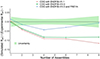 |
Fig. 1. ISSA R2F benchmark results. |
2.4. Time-tagged list-mode detector feature
A new OUTFILE option is available in COG 11.3, which creates a secondary output file listing the time, energy, and score of individual detector events. The default unit for time is seconds and for energy is MeV, but the outfile units can be changed in the BASIC block. This option is invoked by including in the DETECTOR description the line outfile. For example:
  DETECTOR
  number 1
  reaction 2 1
  mask-rea 1 40 $ scores only (n,pg) reactions
  outfile
2.5. Spontaneous fission source features
In addition to the existing random emission time source option available in previous versions, COG 11.3 has a new feature for a spontaneous source for 238U, 238Pu, 240Pu, 242Pu, 244Cm, and 252Cf utilizing the full physics of FREYA. To define a spontaneous fission source simply include particle-type sfs isotope in the SOURCE block under DEFINE ENERGY #, as shown in the example below.
  SOURCE
  npart 10000
  define p 1
  point 0. 0. 0.
  define e 1
  neutron sfs 98252
  inc 1 p 1 e 1
This example yields an energy source of neutrons from spontaneous fission of 252Cf with multiplicity, energy, and direction as determined by FREYA. In the SFS mode, the first call for a source particle triggers a call to the FREYA event routine which returns the number and energies and directions of the neutrons generated by the spontaneous fission event. This data is stored in arrays. The first entry in these arrays is the energy and direction of the first particle, the second entry gives the energy and direction of the second source particle, and so on. COG transports these particles one by one until the array is empty, at which time the FREYA event routine is called again to fill the arrays and the process is repeated.
A second more complete spontaneous fission source is also available. To define this complete spontaneous fission source simply include particle-type fisssrc isotope in the SOURCE block under DEFINE ENERGY #, as shown in the example below.
  SOURCE
  npart 10000
  define p 1
  point 0. 0. 0.
  define e 1
  neutron fisssrc 98252
  Inc 1 p 1 e 1
In the FissSrc mode, a call for a source particle again triggers the FREYA event routine which returns the number and energies and directions of the particles (neutrons in the above example) generated by the spontaneous fission event. Rather than releasing these particles one at a time as in the SFS mode, they are released as a packet with the same generation time and with correlated energies and directions. In the example above, the particle type is neutron which yields a neutron-only source. A particle-type of a photon (or gamma) would yield a photon-only source, and a particle-type of neut-pho would yield a neutron–photon source.
2.6. Effective delayed neutron fraction calculation
To assist users in critical assembly design and reactor physics, COG 11.3 has three estimators for the effective delayed neutron fraction, beta-eff, or βeff. The first is simply the ratio of the number of fissions produced by delayed neutrons divided by the total number of fissions produced by all neutrons [8]. The second is simply the ratio of the number of fission neutrons produced by delayed neutrons divided by the total number of fission neutrons produced by all neutrons [9]. The third estimator is the prompt method [10] estimated as 1 − (kp/keff) where keff is the effective neutron multiplication factor and kp is the effective prompt neutron multiplication factor. Sample results for these estimators are given in Table 1, which are in agreement with experimental errors. These and additional results are published [10]. Note that where no uncertainty is provided in Table 1, this uncertainty is insignificant, i.e., less than 0.5 pcm.
Sample COG 11.3 calculated beta-eff results with ENDF/B-VIII.0 (in pcm).
2.7. Alpha particle transport
Alpha particle transport is available in COG 11.3. The results of COG calculations with comparison to experimental thick target yields, and comparison to the AlfaMC code results, are published [11].
2.8. Deuteron particle transport
Deuteron particle transport is also available in COG 11.3. The results of COG calculations on neutron yield and spectra are in good agreement with published results [12, 13] as shown in Figures 2–3.
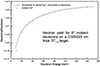 |
Fig. 2. Calculated neutron yield from deuterons on a titanium-tritium target. |
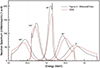 |
Fig. 3. Calculated neutron spectra from deuterons on a titanium-tritium target. |
2.9. General lattice features
A new pre-processor has been added to COG to read and process a string of data between the braces {} within a UNIT definition to generate and automatically run a new input file with the suffix .cnvrt.
2.9.1. Rectangular lattice
If the first symbol in the {} is “x” then the data represents a rectangular lattice which is a UNIT containing a general three-dimensional lattice constructed of multiple USE UNIT statements centered between X, Y, and Z planes defined in the string in a specified arrangement.
In the example given below, sixteen planes are created and numbered at equal spacing from 1501 PLANE X −6.00075 to 1516 PLANE +6.00075, and similarly from 1601 PLANE Y −6.00075 to 1616 PLANE +6.00075. Two planes are specified from 1701 PLANE Z −70. to 1702 PLANE +70. Within the 15 × 15 × 1 spaces defined within 16 × 16 × 2 planes, a series of USE UNIT statements are generated per the patter below in which each unit 1 or 2 is centered between the planes.
  DEFINE UNIT 3 $ 15 × 15 × 1 array of fuel assemblies
  { x 1501 16 [−6.00075 6.00075]
    y 1601 16 [−6.00075 6.00075]
    z 1701 −70. 70.
    fill
  1 1 1 1 1 1 1 1 1 1 1 1 1 1 1
  1 1 1 1 1 1 1 1 1 1 1 1 1 1 1
  1 1 2 1 1 2 1 1 1 2 1 1 2 1 1
  1 1 1 1 1 1 1 2 1 1 1 1 1 1 1
  1 1 1 1 2 1 1 1 1 1 2 1 1 1 1
  1 1 2 1 1 2 1 1 1 2 1 1 2 1 1
  1 1 1 1 1 1 1 1 1 1 1 1 1 1 1
  1 1 1 2 1 1 1 2 1 1 1 2 1 1 1
  1 1 1 1 1 1 1 1 1 1 1 1 1 1 1
  1 1 2 1 1 1 1 1 1 1 1 1 2 1 1
  1 1 1 2 1 1 1 1 1 1 1 2 1 1 1
  1 1 1 1 1 1 1 2 1 1 1 1 1 1 1
  1 1 2 1 1 2 1 1 1 2 1 1 2 1 1
  1 1 1 1 1 1 1 1 1 1 1 1 1 1 1
  1 1 1 1 1 1 1 1 1 1 1 1 1 1 1 }
2.9.2. X-oriented triangular lattice
If the first symbol in the {} is “tri-x” then the data represents an x-oriented triangular lattice. The following is a graphical representation of a 3 × 5 × 1 x-triangular lattice.
   1st point>      1 1 1
 y                1 2 1
 |               2 2 2
 |             1 2 1
 −−−x         1 1 1
 2nd point^      ^3rd point
Four sets of planes are generated: equally spaced x-planes, equally spaced positive-slope planes, equally spaced negative-sloped planes, and two z-planes. These planes define nested cells of hexagonal prisms. In the example below, −3. 3. are the x-y coordinates of the center of the upper left cell, −5. −3. are the coordinates of the center of the lower left cell, 0. −3. are the x-y coordinates of the center of the lower right cell, 3 5 1 are the number of cells per row, the number of cells per column, and the number of cells stacked axially, −70. 70. are the bounding z-planes, 101 201 301 401 are the initial numbers for the four sets of planes, and fill is a keyword indicating that the next entries are the unit numbers filling the array left-to-right, top-to-bottom.
 DEFINE UNIT 5 $ 3 × 5 array
 { tri-x
 −3. 3.
 −5. −3.
 0. −3.
 3 5 1
 −70. 70.
 101 201 301 401
 Fill
 1 1 1
 1 2 1
 2 2 2
 1 2 1
 1 1 1 }
2.9.3. Y-oriented triangular lattice
If the first symbol in the {} is “tri-y” then the data represents a y-oriented triangular lattice. The following is a graphical representation of a 5 × 3 × 1 y-triangular lattice.
    1st point>      1 1 1
 y                1 2 1
 |               2 2 2
 |             1 2 1
 −−−x          1 1 1
 2nd point^       ^3rd point
Four sets of planes are generated: equally spaced y-planes, equally spaced positive-slope planes, equally spaced negative-slope planes, and two z-planes. These planes define nested cells of hexagonal prisms. In the example below, −3. 5. are the x-y coordinates of the center of the upper left cell, −3. 0. are the coordinates of the center of the lower left cell, 3. −5. are the x-y coordinates of the center of the lower right cell, 5 3 1 are the number of cells per row, number of cells per column, and number of cells stacked axially, −70. 70. are the 2 bounding z-planes, 101 201 301 401 are the initial numbers for the four sets of planes, and fill is a keyword indicating that the next entries are the unit numbers filling the array top-to-bottom, left-to-right.
 DEFINE UNIT 6 $ 5 × 3 array
 { tri-y
 −3. 5.
 −3. 0.
 3. −5.
 5 3 1
 −70. 70.
 101 201 301 401
 Fill
 1 1 2 1 1
 1 2 2 2 1
 1 1 2 1 1 }
These features have proven very useful and have been extensively utilized in modeling ICSBEP criticality benchmarks and in criticality safety evaluations of large interacting arrays.
2.10. New parallel processing capabilities
The existing ALPHA (i.e., the inverse reactor period) and CritDetVR features, only available in serial processing mode in previous versions, are now available for parallel processing using MPI in COG 11.3.
2.11. Updated electron transport capabilities
Electron transport in COG 11.3 has been upgraded from EGS4 to EGS5 [14] together with the capability to now call PEGS5 directly from within COG to generate the required EGS5 data library.
2.12. New imaging detector
A new imaging detector feature has been added as a standard feature in COG 11.3 based on an external USERDET feature originally developed by Dr. James Hall. A User Guide [15] describing this feature is published as is a detailed comparison of COG 11.3 to MCNP6.2 sample calculations [16].
2.13. Modernized COG website
The COG website, https://cog.llnl.gov, has been updated and modernized. The top-level page provides a brief description of the code and identifies the twelve particles currently supported as well as information on how to obtain the code and contact the developers using the email address This email address is being protected from spambots. You need JavaScript enabled to view it. . The Publications subpage includes a new search filter based on a keyword or string of keywords. The Registration page has been simplified and all users are encouraged to register. The training webpage contains tutorial documentation as well as information on how to request a training session or course. Lastly, a new subpage devoted to software quality assurance (SQA) is intended to expedite internal and regulatory reviews of compliance with 10 CFR 830, DOE O 414.1D, and NQA-1; and provides users with a comprehensive repository of verification and validation (V&V) test results.
3. Conclusion
COG 11.3 is the culmination of 10 years of development since the previous public release and represents the authors’ commitment to providing users access to the latest nuclear data libraries, advanced physics models, and implementation of new particles, geometry, source, and detector features per user requests.
Acknowledgments
This paper is dedicated to Dr. Richard M. Buck, who retired from the COG code development team in September 2017.
Funding
This work was performed under the auspices of the U. S. Department of Energy by Lawrence Livermore National Laboratory under contract DE-AC52-07NA27344 with sponsorship of the U. S. Department of Energy Nuclear Criticality Safety Program.
Conflicts of interest
The authors declare that they have no competing interests to report.
Data availability statement
Data associated with this article are available from https://cog.llnl.gov
Author contribution statement
David Heinrichs is the Nuclear Criticality Safety Division Leader at LLNL and responsible manager for COG software. Edward Lent is the Principal Computational Physicist for COG software. Chuck Lee is the Principal Computer Scientist for COG software.
References
- D. Heinrichs, S. Kim, D. Biswas, et al., COG 11.1 Code Features for Shielding and Criticality Safety Analysis, LLNL-PROC-642136, Lawrence Livermore National Laboratory, August 15, 2013 [Google Scholar]
- R. Buck, D. Cullen, D. Heinrichs, et al., COG – Publicly Available Now to Criticality Safety Practitioners, in Proceedings of the 8th International Conference on Nuclear Criticality Safety, St. Petersburg, Russia, 2007 (2007) [Google Scholar]
- R. Buck, D. Heinrichs, A. Krass, et al., COG – Special Features of Interest to Criticality Safety Practitioners, Trans. Am. Nucl. Soc. 102, 305 (2010) [Google Scholar]
- J. Verbeke, J. Randrup, R. Vogt, FREYA 2.0: New Developments in Fission Chain Modeling, in Proceedings of the Institute for Nuclear Materials Management Annual Meeting, Palm Desert, CA, USA, July 2017 (2017) [Google Scholar]
- D. Heinrichs, J. Burch, B. Hudson, et al., Design, Development and Utilization of the New LLNL Inherently Safe Subcritical Assembly (ISSA), LLNL-CONF-670257, Lawrence Livermore National Laboratory, May 4, 2015 [Google Scholar]
- A. Nelson, S. Kim, J. Verbeke, et al., Subcritical Measurements of Water-Moderated Highly Enriched Uranium Oxide MTR Type Fuel, NEA/NSC/DOC/(95)03IX, FUND-LLNL-ALPHAN-HE3-MULT001, Rev. 0, Nuclear Energy Agency, OECD, May 31, 2019 [Google Scholar]
- A. Nelson, W. Monange, S. Kim, et al., Fundamental Physics Subcritical Neutron Multiplicity Benchmark Experiments Using Water Moderated Highly Enriched Uranium Fuel, LLNL-CONF-778008, Lawrence Livermore National Laboratory, June 14, 2019 [Google Scholar]
- R. Meulekamp, S. van der Marck, Calculating the Effective Delayed Neutron Fraction with Monte Carlo, Nucl. Sci. Eng. 152, 142 (2006) [CrossRef] [Google Scholar]
- S. Pearlstein, The Effective Delayed Neutron Fraction for Bare-Metal Criticals, Nucl. Tech. 128, 482 (1999) [Google Scholar]
- D. Heinrichs, E. Lent, W. Zywiec, COG Beta-Effective Benchmarks, LLNL-TR-843852, Lawrence Livermore National Laboratory, December 20, 2022 [Google Scholar]
- E. Lent, Alpha Transport in COG, LLNL-TR-655365, Lawrence Livermore National Laboratory, June 4, 2014 [Google Scholar]
- E. Gunnerson, G. James, On the Efficiency of the Reaction H3(d,n)He4 in Titanium Tritide Bombarded with Deuterons, Nucl. Instr. Meth. 8, 173 (1960) [CrossRef] [Google Scholar]
- A. Milocco, A. Trkov, Modelling of the Production of Source Neutrons from Low-Voltage Accelerated Deuterons on Titanium-Tritium Targets, Sci. Technol. Nucl. Install. 2008, 340282 (2008) [CrossRef] [Google Scholar]
- H. Hirayama et al., The EGS5 Code System, SLAC-R-730, KEK-2005-8, January 13, 2016 [Google Scholar]
- M.-A. Descalle, COG Imaging Detector User Guide by Jim Hall and Ed Lent, LLNL-PRES-843321, Lawrence Livermore National Laboratory, May 14, 2020 [Google Scholar]
- J. Hall, Neutron Image Simulations – MCNP6 vs. COG11, LLNL-PRES-831931, Lawrence Livermore National Laboratory, February 2022 [Google Scholar]
Cite this article as: David Heinrichs, Edward Lent, Chuck Lee. COG 11.3 new features, EPJ Nuclear Sci. Technol. 11, 2 (2025) https://doi.org/10.1051/epjn/2024017
All Tables
All Figures
|
Fig. 1. ISSA R2F benchmark results. |
| In the text | |
|
Fig. 2. Calculated neutron yield from deuterons on a titanium-tritium target. |
| In the text | |
|
Fig. 3. Calculated neutron spectra from deuterons on a titanium-tritium target. |
| In the text | |
Current usage metrics show cumulative count of Article Views (full-text article views including HTML views, PDF and ePub downloads, according to the available data) and Abstracts Views on Vision4Press platform.
Data correspond to usage on the plateform after 2015. The current usage metrics is available 48-96 hours after online publication and is updated daily on week days.
Initial download of the metrics may take a while.