| Issue |
EPJ Nuclear Sci. Technol.
Volume 2, 2016
|
|
|---|---|---|
| Article Number | 16 | |
| Number of page(s) | 10 | |
| DOI | https://doi.org/10.1051/epjn/2016010 | |
| Published online | 01 April 2016 | |
https://doi.org/10.1051/epjn/2016010
Regular Article
Thermalhydraulics of advanced 37-element fuel bundle in crept pressure tubes
Korea Atomic Energy Research Institute, 989-111 Daedukdaero, Yuseong-gu, Taejon, 305-353, Korea
⁎ e-mail: This email address is being protected from spambots. You need JavaScript enabled to view it.
Received:
30
September
2015
Received in final form:
20
January
2016
Accepted:
4
February
2016
Published online:
1
April
2016
Abstract
A CANDU-6 reactor, which has 380 fuel channels of a pressure tube type, is suffering from aging or creep of the pressure tubes. Most of the aging effects for the CANDU primary heat transport system were originated from the horizontal crept pressure tubes. As the operating years of a CANDU reactor proceed, a pressure tube experiences high neutron irradiation damage under high temperature and pressure. The crept pressure tube can deteriorate the Critical Heat Flux (CHF) of a fuel channel and finally worsen the reactor operating performance and thermal margin. Recently, the modification of the central subchannel area with increasing inner pitch length of a standard 37-element fuel bundle was proposed and studied in terms of the dryout power enhancement for the uncrept pressure tube since a standard 37-element fuel bundle has a relatively small flow area and high flow resistance at the central region. This study introduced a subchannel analysis for the crept pressure tubes loaded with the inner pitch length modification of a standard 37-element fuel bundle. In addition, the subchannel characteristics were investigated according to the flow area change of the center subchannels for the crept pressure tubes. Also, it was discussed how much the crept pressure tubes affected the thermalhydraulic characteristics of the fuel channel as well as the dryout power for the modification of a standard 37-element fuel bundle.
© J.H. Park and Y.M. Song, published by EDP Sciences, 2016
 This is an Open Access article distributed under the terms of the Creative Commons Attribution License (http://creativecommons.org/licenses/by/4.0), which permits unrestricted use, distribution, and reproduction in any medium, provided the original work is properly cited.
1 Introduction
A CANDU-6 fuel bundle is composed of the 37 fuel elements. Spacers and bearing pads are used to prevent direct contact of the fuel elements and/or the pressure tube during the operation. In addition, the end plates are welded on both sides of the fuel bundle to configure a bundle geometry, as shown in Figure 1. For a CANDU-6 reactor such as Wolsung nuclear power plant in Korea, twelve fuel bundles are loaded into a horizontal pressure tube. Because the fuel bundles sit on the bottom inside of the horizontal pressure tube, an open gap on the top section of the fuel channel exists even at the beginning of the reactor operation. Hence, the coolant tends to flow into the open gap rather than the fuel bundle section because of the low flow resistance in the open gap.
One of the most important aging parameters of a CANDU reactor is originated from the horizontal crept pressure tubes. When the reactor becomes older, an open gap becomes wider because it is expanding radially as well as axially during its life time, as a result of the creep of the pressure tube, which has experienced with high neutron irradiation damage under high temperature and pressure exposure conditions. It allows a by-pass flow on the top section inside the pressure tube. Hence, the crept pressure tube deteriorates the Critical Heat Flux (CHF) of the fuel channel and finally decreases the reactor operating performance.
During the last decades, there have been several studies to overcome the CHF deterioration caused by the pressure tube creep. One of the studies to enhance the CHF was the development of a CANFLEX fuel bundle, which is composed of two pin sizes and attached CHF enhancement buttons on the surfaces of 43 element fuels [1]. It is known that the critical channel power (CCP) enhancement of the CANFLEX fuel bundle can achieve about 4%, 8%, and 13% for the 0%, 3.3% and 5.1% crept pressure tubes, respectively, compared to the standard 37-element fuel bundle (37S fuel bundle) [2]. However, it has not been commercialized yet.
On the other hand, it is known that most CHF of a 37S fuel bundle have occurred at the central area because it has a relatively small flow area and high flow resistance at the peripheral subchannels of its center element compared to the other subchannels [3]. Considering such CHF characteristics of a 37S fuel bundle, there can be two approaches to enlarge the flow areas of the peripheral subchannels of a center element to enhance the CHF. To increase the center subchannel areas, one approach was the reduction of the diameter of a center element [4], and the other was an increase of the inner pitch length [5]. The former can increase the total flow area of a fuel bundle and redistributes the power density of all fuel elements as well as the CHF. On the other hand, the latter can reduce the gap between the elements located in the middle and inner pitch circles owing to the increasing inner pitch circle. This can also affect the enthalpy redistribution of the fuel bundle and finally enhance the CHF or dryout power. Both studies were found to be very effective at enhancing the CHF or dryout power through moving the first CHF location occurring at the center subchannels to the other subchannels of a 37S fuel bundle [6]. CHF experiments have been performed at Stern Laboratory to introduce a 37S fuel bundle with a small center element to the commercial reactors [4]. But the detail information of its CHF characteristics has not been published yet.
Recently, a 37S fuel bundle with the inner pitch length modification was studied and its dryout power enhancement was introduced in reference [5], but the creep effects of the pressure tube on the dryout power were not discussed yet. This paper investigated the pressure tube creep effects of the 37A fuel bundle on the dryout power with increasing the inner pitch length. In addition, the thermalhydraulic characteristics of the crept fuel channel were also presented.
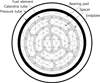 |
Fig. 1 The configuration of the CANDU fuel channel with a 37-element fuel bundle. |
2 Analysis modelling
2.1 37A fuel bundle
A 37S fuel bundle is composed of 37-element fuels and four pitch circles such as the center, inner, middle, and outer pitches to configure the bundle geometry, as shown in Figure 1. Recently, a 37S fuel bundle with the inner pitch length modification (here-in-after a 37A fuel bundle) was proposed to enhance the CHF of a 37S fuel bundle [5]. The 37A fuel bundle is defined as a 37S fuel bundle with an inner pitch length modification, which is increased from 14.98 to 15.38 mm in 0.1 mm steps to enlarge the center subchannel area. Each pitch length of the 37S and 37A fuel bundles is summarized in Table 1.
Pitch lengths of the 37S and 37A fuel bundles.
2.2 Pressure tube creep
The pressure tube of a CANDU reactor is made of Zr-2.5%Nb alloy. Since it is vulnerable to the irradiation of the fast neutron flux, it will be crept during the reactor operation. When the reactor operating age increases, the pressure tube will be expanded radially as well as axially. The radial creep of the pressure tube makes its diameter increase. Because a CANDU fuel bundle sits on the inside of a horizontal pressure tube during the dwelling time in the reactor, the flow area at the upper section becomes larger than at the bottom section. It is known that the creep rates of the pressure tube for a CANDU reactor can be increased to 3.3% and 5.1% at the middle and end of its lifetime, respectively. In addition, it will become more serious on the CHF deterioration as its diameter increases. As shown in Figure 2, the flow area of the outer subchannels numbered from #43 to #60 can be increased as the pressure tube is crept or its diameter is increased. But the flow areas of the upper subchannels (i.e. green colored region in Fig. 2) of the fuel bundle can be increased more than those of the lower subchannels (i.e. pink colored region in Fig. 2) because the fuel bundle sits inside of the pressure tube horizontally. These geometric characteristics can divert the coolant from the bundle section to the wider upper section due to low flow resistance. Also, such a flow distortion from bundle to upper sections can become more serious for the higher creep rate of the pressure tube. This study considered such a radial creep rather than an axial creep, which mainly affects the thermalhydraulic performance of the fuel channel.
Figure 3 shows the typical diameter profile of the pressure tube along the axial location of the fuel channel for the creep rates such as 0%, 3.3%, and 5.1%. It has a skewed cosine-shaped profile along the fuel channel. Thus, the subchannel analyses were conducted for the 3.3% and 5.1% crept pressure tubes as well as the 0% crept pressure tube as a reference. The maximum diameters for the 3.3% crept and 5.1% crept tubes were located at an axial distance of 4.3 m and 4.8 m from the entrance of the fuel channel, respectively, as shown in Figure 3. These profiles representatively simulate the prototypical fuel channels with plant ageing and were used for the water CHF tests as well [1].
To investigate the flow area changes in the top section due to the pressure tube creep and bundle eccentricity horizontally, the flow area distortion factor, ξ
d
, is defined as follows: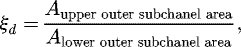 where the upper and lower outer subchannel areas of a 37 fuel bundle are shown by the shaded green and pink color areas in Figure 2, respectively. The ξ
d
for the 0%, 3.3% and 5.1% crept pressure tubes were shown to be 1.21, 1.69, and 1.91, respectively, while the total flow area was increased by 16% and 26% for the 3.3% and 5.1% crept pressure tubes at the axial peak creep location, as shown in Figure 4.
where the upper and lower outer subchannel areas of a 37 fuel bundle are shown by the shaded green and pink color areas in Figure 2, respectively. The ξ
d
for the 0%, 3.3% and 5.1% crept pressure tubes were shown to be 1.21, 1.69, and 1.91, respectively, while the total flow area was increased by 16% and 26% for the 3.3% and 5.1% crept pressure tubes at the axial peak creep location, as shown in Figure 4.
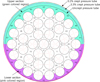 |
Fig. 2 Subchannel configuration of a 37-element fuel bundle in the crept pressure tubes. |
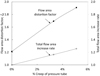 |
Fig. 4 Flow area distortion according to the pressure tube creep. |
2.3 Subchannel analysis
A subchannel analysis was performed for a 37S fuel bundle with/without the inner pitch length modification using the ASSERT PV code [7]. The ASSERT code is originated from the COBRA-IV computer program [8,9]. It has been developed to meet the specific requirements for the thermalhydraulic analysis of two-phase flow in horizontally oriented CANDU fuel bundles. Especially, it is distinguished from COBRA-IV in terms of following features [7]:
-
the lateral momentum equation is also considered with the gravity term in order to allow gravity driven lateral recirculation;
-
the five-equation model was applied to the two-phase flow model in consideration of the thermal non-equilibrium and the relative velocity of the liquid and vapour phases. Thermal non-equilibrium is calculated from the two-fluid energy equations for the liquid and vapour. Relative velocity is obtained from semi-empirical models;
-
the relative velocity model accounts for the different velocities of the liquid and vapour phases in both axial and lateral directions. As well, the lateral direction modelling contains features that consider:
-
gravity driven phase separation or buoyancy drift in horizontal flow,
-
void diffusion turbulent mixing,
-
void drift (void diffusion to a preferred distribution).
-
To find the subchannel and axial locations of the first CHF occurrence in a fuel channel, the calculation will continue until the convergence tolerance is reached at the specified criteria, ‘ODVTOL’ in the ASSERT code. Once the first CHF for the given mass flow and inlet temperature has occurred at any subchannel and axial location during iteration, the calculation is stopped and all flow parameters are printed out. Onset-of-dryout iteration for the first CHF occurrence can be found as follows: (1)where ‘MCHFLO’ and ‘MCHFUP’ are the lower and upper bounds, respectively, for the target minimum CHFR (MCHFR), and ‘MCHFR’ is the minimum CHF ratio and is defined as:
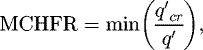 (2)where
  is the CHF, and
  is the zonal heat flux. ‘ODVTOL’ is the relative convergence tolerance on the iteration parameter, which is defined as follows:
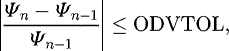 (3)where Ψ is the iteration parameter and n is the iteration number. Ψ and n are given as 1.00004 and 20, respectively, for the present calculation.
Generally, the subchannel can be defined by the hypothetical line connected from one rod center to an adjacent rod center. Hence, the subchannels of a 37S fuel bundle are composed of three types, i.e., triangular, rectangular, and wall subchannels. Those subchannel numbers in Figure 2 are as follows:
-
rectangular: 11, 13, 15, 17, 19, 23, 27, 31, 35, 39;
-
wall: 43 to 60;
-
triangular: the remainder.
The number of rods and subchannels are 37 and 60, respectively. For the present subchannel analysis, the full subchannel geometry was considered.
For a CANDU-6 reactor, the coolant temperature at the reactor inlet header and the coolant pressure at reactor outlet header were designed as 262 °C and 10.0 MPa respectively under D2O condition and it was limited to 268 °C during the lifetime [10]. If the temperature of the reactor inlet header approaches the limited value, the steam generator should be generally cleaned to lower the reactor inlet head temperature. And the reference flow rate in the fuel channel was designed as 24 kg/s and the maximum flow rate of the fuel channel can be estimated to be about 28 kg/s [10]. Hence, the present subchannel analysis was performed using the boundary conditions, which are three inlet temperatures, i.e., 256 °C, 262 °C, and 268 °C, four mass flows, 22 kg/s, 24 kg/s, 26 kg/s, and 28 kg/s and the same outlet pressure condition, 10.0 MPa with heavy water coolant to consider the actual reactor operating conditions.
3 Results and discussions
3.1 Pressure tube creep effect on dryout power of a 37S fuel bundle
The subchannel analysis for a 37S fuel bundle was performed to investigate the dryout power according to the increase of the creep rates of the pressure tube from 0% to 3.3% and 5.1% using the ASSERT code with a CHF look-up table [11]. For comparison of the dryout powers of the crept pressure tubes with those of the uncrept pressure tube, the dryout power ratio for a 37S fuel bundle, r
DP,37S
, was defined as follows: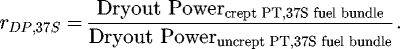
The results of the dryout power ratios for a 37S fuel bundle, r DP,37S , were plotted in Figure 5. As shown in Figure 5, r DP,37S decreases with an increase in the creep rates of the pressure tube for all flow conditions while r DP,37S increases with an increase in the flow rate as expected. The minimum r DP,37S was found to be 0.80 at 22 kg/s of the low flow condition. It means that the dryout power for 5.1% crept pressure tube and 22 kg/s of mass flow condition was about 20% lower than that for the uncrept pressure tube due to the by-pass flow at upper section of the fuel bundle as described in the above. Also, it can be noted that the high flow rate in the fuel channel makes the coolant have a higher mixing among the subchannels, and the effects of the flow area distortion factor, ξ d , on the dryout power become less significant for the high flow rate conditions. And the variations of the dryout power ratio for different inlet temperatures were not significant as shown in Figure 5.
Figures 6, 7 and 8 show the void fraction distributions of the subchannels at the first CHF location for the 0%, 3.3%, and 5.1% crept pressure tubes, respectively. As shown in Figure 6, the first CHF occurred at the subchannel #1 under 256 °C and 268 °C inlet temperature conditions. The void fractions at the CHF location or subchannel #1 are 0.650 and 0.669 for 256 °C and 268 °C inlet temperatures respectively and those values are the highest among all the subchannels.
On the other hand, the first CHFs for the 3.3% crept pressure tube occurred at the same location as for the uncrept pressure tube, but the void fraction for 256 °C inlet temperature condition is 0.797 and very close to that for 268 °C inlet temperature condition as shown in Figure 7. For the 5.1% crept pressure tube, the first CHFs for both inlet temperature conditions were occurred at subchannel #7, although the void fraction at the subchannel #7 was lower than that of subchannel #1. Also, the axial CHF locations for both inlet temperature conditions were the same, 524.98 mm which was the location just after the middle bearing pad of the 11th fuel bundle.
In addition, the void fractions of the outer subchannels were lower than those of other subchannels and it was caused by non-heated wall effect of the pressure tube. And the void fractions of the higher inlet temperature condition are higher than those of the lower inlet temperature at the first CHF location.
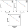 |
Fig. 5 Dryout power ratios for a 37S fuel bundle. |
 |
Fig. 6 Void fraction of a 37S fuel bundle for the uncrept pressure tube at 24 kg/s. |
 |
Fig. 7 Void fraction of a 37S fuel bundle for the 3.3% crept pressure tube at 24 kg/s. |
 |
Fig. 8 Void fraction of a 37S fuel bundle for the 5.1% crept pressure tube at 24 kg/s. |
3.2 Pressure tube creep effect on dryout power of a 37A fuel bundle
The subchannel analysis was performed for a 37A fuel bundle for the 3.3% and 5.1% crept pressure tubes as well as the 0% crept pressure tube. It is focused on examining the diameter increase effect of the pressure tube caused by the irradiation creep. For a comparison of the dryout powers of the 37A and 37S fuel bundles, the dryout power ratio for a 37A fuel bundle, r
DP,37A
, was defined as follows: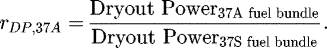
The results were plotted in Figures 9, 10 and 11 for uncrept, 3.3%, and 5.1% pressure tubes, respectively. As shown in Figure 9, r DP,37A for the 0% crept pressure tube under 256 °C of the inlet temperature condition is increasing up to 15.18 mm of the inner pitch length, and decreasing for further increases of the inner pitch length. The maximum r DP,37A was found to be 1.057 at 15.18 mm of the inner pitch length under 28 kg/s of the highest flow condition. The behaviors of r DP,37A for all inlet temperature conditions are similar but the dependencies of r DP,37A on the mass flows are a little significant.
For the 3.3% crept pressure tube or 106.79 mm of its diameter, the r DP,37A for each inlet temperature and mass flow is shown in Figure 10. The maximum r DP,37A for 24 kg/s of the mass flow appeared at 15.28 mm of the inner pitch length, while the maximum r DP,37A for 26 kg/s and 28 kg/s of the mass flows were found at 15.18 mm of the inner pitch length. It means that the inner pitch length to give the maximum r DP,37A may tend to be decreased as increasing the mass flow. This trend can be found more distinctly at the case of the 5.1% crept pressure tube as shown in Figure 11. And the maximum r DP,37A was 1.07 for the case of 15.28 mm of the inner pitch length under 24 kg/s and 268 °C of the flow conditions as shown in Figure 10c. The effects of the inner pitch length on r DP,37A for the 3.3% crept pressure tube were more significant than those for the 0% crept pressure tube. It is noted that the modification of the inner pitch length can be more effective as increasing the pressure tube diameter.
For the 5.1% crept pressure tube, 108.65 mm of its diameter, the r DP,37A for each inlet temperature and mass flow is shown in Figure 11. The maximum r DP,37A appeared at the higher inner pitch length than the 0% or 3.3% crept cases for all flow conditions, and was 1.065 at 15.28 mm for 28 kg/s of the highest flow conditions, as shown in Figure 11c. However, r DP,37A for the lower flow conditions such as 22 kg/s and 24 kg/s was monotonically increased by increasing the inner pitch length. In addition, the r DP,37A for all conditions was increased with an increase of the mass flow. The 15.38 mm of the inner pitch length is the maximum allowable because of the limitation of the minimum gap between the inner and middle fuel elements as found in reference [10]. It should be noted that the optimum design of the inner pitch length to achieve the maximum r DP,37A is dependent on not only the creep rates of the pressure tube but the flow conditions. In order to determine the optimum inner pitch length, at first, it should be known which mass flow or inlet temperature is more concerned on overcoming the power de-rating of a CANDU reactor.
On the other hand, the uncertainty on the above calculation results of the dryout power could exist for both a 37S fuel bundle and its modifications, but it was not considered because of the sensitivity studies for a 37S fuel bundle and its modifications.
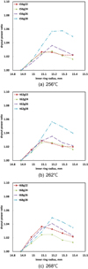 |
Fig. 9 Dryout power ratio of a 37A fuel bundle for 0% crept pressure tube. |
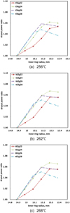 |
Fig. 10 Dryout power ratio of a 37A fuel bundle for 3.3% crept pressure tube. |
 |
Fig. 11 Dryout power ratio of a 37A fuel bundle for 5.1% crept pressure tube. |
3.3 Inner pitch length effect on the CHF location for crept pressure tubes
Since the subchannel locations of the first CHF occurrence for the 0% crept pressure tube were found in reference [5], the present study only discusses the locations of the first CHF occurrence for the crept pressure tubes. The subchannel locations of the first CHF occurrence for the 3.3% and 5.1% crept pressure tubes were found and summarized in Tables 2 and 3, respectively. For a 37S fuel bundle, which has a 14.88 mm inner pitch length, all of the first CHFs for the 3.3% crept case occurred at the center subchannel #1 as those for the 0% crept pressure tube in reference [5].
When the inner pitch length is increasing, the first CHF location moves to the inner or middle subchannels such as #10 or #33 (see Fig. 2 for the subchannel numbers). For the 14.88 mm inner pitch length, the subchannels of the first CHF occurrence for the 5.1% crept case were located at the inner subchannel #7 or the center subchannel #1, which are different from those of the 3.1% crept case. This is caused by the higher by-pass flow at the open top section of the fuel bundle, which has a flow area increase of 91% higher than that of the outer lower subchannel as discussed in Section 2.2.
From the above results, it should be noted that the dryout power should be increased by virtue of moving the subchannel locations of the first CHF occurrence from the center subchannel to the other subchannel, according to enlarging the center subchannel area by increasing the inner pitch length. In addition, it is revealed that the favorable effects of the large center subchannel area on the dryout power become more significant for the higher creep rate of the pressure tube.
Subchannel location of the 1st CHF occurrence for 3.3% crept pressure tube.
Subchannel location of the 1st CHF occurrence for 5.1% crept pressure tube.
4 Conclusions
A subchannel analysis using the ASSERT code was performed for the 37S and 37A fuel bundles with the crept pressure tubes to investigate the dryout power changes in terms of the inner pitch length modification and the pressure tube diameter increase.
It was concluded that the inner pitch length modification of a 37S fuel bundle could make the dryout power of the crept pressure tube to be enhanced more than that of the uncrept pressure tube. The maximum dryout power ratio is obtained at a higher inner pitch length. In addition, it was shown that the favorable effects of the large center subchannel area on the dryout power become more significant for the higher creep rate of the pressure tube, that is, the modification of the inner pitch length can be more effective as increasing the pressure tube diameter.
From the present analysis, it was noted that the dryout power could be enhanced by virtue of moving the center subchannel to the other subchannels of the first CHF occurrence if the center subchannel area could be enlarged by increasing the inner pitch length. And it was shown that the optimum value of the inner pitch length to achieve the maximum dryout power ratio is dependent on not only the creep rates of the pressure tube but the flow conditions. In order to determine the optimum inner pitch length, it should be known which mass flow or inlet temperature is more concerned on overcoming the power de-rating of a CANDU reactor.
Acknowledgments
This work was supported by the National Research Foundation of Korea (NRF) grant funded by the Korea government (Ministry of Science, ICT, and Future Planning) (No. NRF-2012M2A8A4025960).
References
- G.C. Dimmick, W.W.R. Inch, J.S. Jun, H.C. Suk, G.I. Hadaller, R.A. Fortman, R.C. Hayes, Full scale water CHF testing of the CANFLEX bundle, in Proceeding of the 6th International Conference on CANDU fuel , Niagara Falls, Ontario, Canada (1999), pp. 103–113 [Google Scholar]
- J.S. Jun, Thermalhydraulic evaluations for CANFLEX bundle with natural or recycled uranium fuel in the uncrept and crept channels of a CANDU-6 reactor, Nucl. Eng. Technol. 35 , 479 (2005) [Google Scholar]
- L.K.H. Leung, F.C. Diamayuga, Measurements of critical heat flux in CANDU 37-element bundle with a steep variation in radial power profile, Nucl. Eng. Des. 240 , 290 (2010) [CrossRef] [Google Scholar]
- A. Tahir, Y. Parlatan, M. Kwee, W. Liauw, G. Hadaller, R. Fortman, Modified 37-element bundle dryout, in NURETH-14 , Hilton Toronto Hotel, Toronto, Ontario, Canada (2011) [Google Scholar]
- J.H. Park, Y.M. Song, The effect of inner ring modification of standard 37-element fuel on CHF enhancement, Ann. Nucl. Energy 70 , 135 (2014) [CrossRef] [Google Scholar]
- J.H. Park, J.Y. Jung, E.H. Ryu, CHF Enhancement of Advanced 37-element Fuel bundles, Sci. Technol. Nucl. Installations 2015 , 243867 (2015) [Google Scholar]
- M.B. Carver, J.C. Kiteley, R.Q.N. Zou, S.V. Junop, D.S. Rowe, Validation of the ASSERT subchannel code; prediction of critical heat flux in standard and nonstandard CANDU bundle geometries, Nucl. Technol. 112 , 299 (1995) [Google Scholar]
- C.L. Wheeler et al., COBRA-IV-I: an interim version of COBRA for thermal-hydraulic analysis of rod-bundle nuclear fuel elements and cores, Battelle Pacific Northwest Laboratories Report, BNWL-1962, 1976 [Google Scholar]
- C.W. Stewart et al., COBRA-IV: The model and the method, Battelle Pacific Northwest Laboratories Report, BNWL-2214, 1977 [Google Scholar]
- AECL, Fuel Design Manual for CANDU-6 reactors, DM-XX-37000-001, 1989 [Google Scholar]
- D.C. Groeneveld, L.K.H. Leung, P.L. Kirillov, V.P. Bobkov, I.P. Smogalev, V.N. Vinogradov, X.C. Huang, E. Royer, The 1995 look-up table for critical heat flux in tubes, Nucl. Eng. Des. 163 , 1 (1995) [Google Scholar]
Cite this article as: Joo Hwan Park, Yong Mann Song, Thermalhydraulics of advanced 37-element fuel bundle in crept pressure tubes, EPJ Nuclear Sci. Technol. 2, 16 (2016)
All Tables
All Figures
|
Fig. 1 The configuration of the CANDU fuel channel with a 37-element fuel bundle. |
| In the text | |
|
Fig. 2 Subchannel configuration of a 37-element fuel bundle in the crept pressure tubes. |
| In the text | |
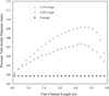 |
Fig. 3 Axial profile of the pressure tube diameter creep [1]. |
| In the text | |
|
Fig. 4 Flow area distortion according to the pressure tube creep. |
| In the text | |
|
Fig. 5 Dryout power ratios for a 37S fuel bundle. |
| In the text | |
|
Fig. 6 Void fraction of a 37S fuel bundle for the uncrept pressure tube at 24 kg/s. |
| In the text | |
|
Fig. 7 Void fraction of a 37S fuel bundle for the 3.3% crept pressure tube at 24 kg/s. |
| In the text | |
|
Fig. 8 Void fraction of a 37S fuel bundle for the 5.1% crept pressure tube at 24 kg/s. |
| In the text | |
|
Fig. 9 Dryout power ratio of a 37A fuel bundle for 0% crept pressure tube. |
| In the text | |
|
Fig. 10 Dryout power ratio of a 37A fuel bundle for 3.3% crept pressure tube. |
| In the text | |
|
Fig. 11 Dryout power ratio of a 37A fuel bundle for 5.1% crept pressure tube. |
| In the text | |
Current usage metrics show cumulative count of Article Views (full-text article views including HTML views, PDF and ePub downloads, according to the available data) and Abstracts Views on Vision4Press platform.
Data correspond to usage on the plateform after 2015. The current usage metrics is available 48-96 hours after online publication and is updated daily on week days.
Initial download of the metrics may take a while.