| Issue |
EPJ Nuclear Sci. Technol.
Volume 5, 2019
Progress in the Science and Technology of Nuclear Reactors using Molten Salts
|
|
|---|---|---|
| Article Number | 18 | |
| Number of page(s) | 11 | |
| Section | Safety Evaluation | |
| DOI | https://doi.org/10.1051/epjn/2019031 | |
| Published online | 11 November 2019 | |
https://doi.org/10.1051/epjn/2019031
Regular Article
Application of the lines of defence method to the molten salt fast reactor in the framework of the SAMOFAR project
1
Framatome, 10 rue Juliette Récamier, 69006 Lyon, France
2
LPSC-IN2P3-CNRS, UJF, Grenoble INP, 53 rue des Martyrs, 38026 Grenoble, France
3
NEMO Group, DENERG, Politecnico di Torino, C.so Duca degli Abruzzi 24, 10129 Torino, Italy
* e-mail: This email address is being protected from spambots. You need JavaScript enabled to view it.
Received:
3
May
2019
Received in final form:
19
July
2019
Accepted:
10
September
2019
Published online: 11 November 2019
Abstract
The Molten Salt Fast Reactor (MSFR) with its liquid circulating fuel and its fast neutron spectrum calls for a new safety approach and adaptation of the analysis tools. In the frame of the Horizon2020 program SAMOFAR (Safety Assessment of the Molten Salt Fast Reactor), a safety approach suitable for Molten Salt Reactors has been developed and is now applied to the MSFR. For this purpose, the Lines of Defence (LoD) method is selected to drive the design consistently with the Defence in Depth principle. This paper presents the main characteristics of the method, along with some practical guidelines to apply it to the specific case of the MSFR; moreover, some initiating events are analyzed through the implementation of the LoD tool. The outcomes of this analysis drive the design evolution.
© S. Beils et al., published by EDP Sciences, 2019
 This is an Open Access article distributed under the terms of the Creative Commons Attribution License (http://creativecommons.org/licenses/by/4.0), which permits unrestricted use, distribution, and reproduction in any medium, provided the original work is properly cited.
1 Introduction
Nuclear power is recognized as an outstanding source for base load low-carbon electricity production and it is included in all energy scenarios in the European Energy Roadmap 2050. The development of fast breeder reactors and associated fuel cycles is fundamental to improve the utilization of nuclear fuel.
New generation nuclear reactors are expected to be designed with the highest safety standards. In that frame, there is an incentive to look for nuclear concepts with enhanced intrinsic safety features. Optimized waste management is also an important goal for the new generation of nuclear systems.
Together with five other nuclear energy systems, the Molten Salt Fast Reactor (MSFR) was selected by the Generation IV International Forum (GIF) due to its promising design and unique safety features [1,2] and is currently studied in the frame of the Horizon2020 program SAMOFAR (Safety Assessment of the Molten Salt Fast Reactor). Its main objective is “to prove the reliability of the innovative safety concepts of the MSFR by advanced experimental and numerical techniques, to deliver a breakthrough in nuclear safety and optimal waste management” [3].
Using the Functional Failure Mode and Effects Analysis (FFMEA) and the Master Logic Diagram (MLD), a list of accidents initiators has been identified for the plant state corresponding to the nominal conditions during power production [4,5,6,7]. In parallel, a list of design key-points that are relevant for safety and that should be further documented has been provided [6]. Successively, the method of the Lines of Defence (LoD) has been applied for some of the selected initiating events. This method helps the designer to determine whether sufficient safety provisions are put in place for a given risk with the aim of ensuring that every accidental evolution of the reactor state is always prevented by a minimum set of homogenous (in number and quality) safety provisions − the Lines of Defence − before a given situation may arise. The objective of this paper is to describe the implementation of the Lines of Defence method and to present its first results and the way it drives the on-going design work, consistently with the Defence in Depth principle.
In Section 2, a brief description of the MSFR current design considered in the SAMOFAR project is presented [8]. Afterwards, in Section 3 the methodology used to perform the work is summarised. Section 4 presents the first results. In the end, some conclusions and further perspectives are reported.
2 Description of the system
2.1 General description
The reference MSFR is a 3 GW thermal power reactor with a fast neutron spectrum and operated in the thorium fuel cycle. The plant includes three main circuits involved in power generation: the fuel circuit, the intermediate circuit and the energy conversion circuit, which is connected to the electrical grid and the heat sink. The main characteristic of the MSFR is the use of a liquid fuel, in the form of a molten salt, which circulates in the fuel circuit. Therefore, this molten salt plays both the roles of fuel and heat transport. The fuel circuit is not pressurized. The selected fuel salt is a binary fluoride salt with, in its initial composition, 77.5 mol% of lithium fluoride; the remaining 22.5 mol% are a mix of heavy nuclei fluorides including fissile and fertile matters. The properties of the fuel salt and the characteristics of the fuel circuit, considered for the following analysis, are listed in Table 1. As presented in Figure 1, the fuel circuit geometry [8,12] includes the core vessel used as a container for the fuel salt, in which 16 cooling sectors are disposed circumferentially. The 18 m3 of fuel salt are equally distributed between the core (central area where most of the fissions occur) and the cooling sectors. Each sector comprises a heat exchanger, a pump, a gas processing system, and a fertile blanket tank. Neutron shielding is positioned between the breeding blanket and the heat exchangers to protect the heat exchangers from neutron radiation. In addition, reflectors are located at the bottom and the top of the vessel to protect the structures located outside the core. The fuel circuit structures are made of Hastelloy N, which is a nickel based alloy specifically developed for fluoride molten salt reactor [13] taking benefit of the experience feedback from Oak Ridge National Laboratory (ORNL) in the 50's and 60's with the Aircraft Reactor Experiment (ARE) and Molten Salt Reactor Experiment (MSRE).
The fuel circuit is connected to the intermediate circuit through the heat exchangers. Four intermediate circuits are foreseen, each of them feeding four cooling sectors. The structural material of the intermediate circuit is not selected yet.
The fuel salt undergoes two types of treatment: an online gas bubbling in the core and a remote mini-batch processing on-site. The bubbling system is used to clean the salt from gaseous fission products and metallic particles. The gas is injected at the bottom of the core and recovered at the top to be cleaned up in the gas processing unit before being re-injected in the core. The chemical fuel processing is performed in the processing unit, in a separated building on the same site. Fuel samples are daily extracted/injected in the fuel circuit, during the reactor operation, thanks to the sampling system. In fact, fuel salt samplings are regularly performed to control and adjust the fuel chemical composition and its fissile/fertile inventory.
Figure 2 gives an overview of the different systems and their localization in the reactor building. The fuel circuit is connected to other auxiliary and safety systems. In particular, there are two types of draining systems: the routine draining system to the storage areas and the Emergency Draining System (EDS) [8,12]. The routine draining system, triggered only by active means, is used to transfer the fuel from the core vessel to storage areas. On the other hand, the EDS is located under the core vessel to allow a gravitational draining. The fuel circuit is connected to this system through valves located in the lower part of the core vessel. Several types of valves are foreseen, including active valves, such as valves automatically triggered (for example by the detection of a too high temperature/pressure), or by operator action and passive valves, such as fusible valves triggered by the fusion or the rupture of a component under too high temperature conditions. In addition, a core catcher is located in the lower part of the reactor vessel. The core catcher is notably able to recover leaking fuel salt in case of EDS failure. It is based on the spreading of the fuel on a large area and on the mixing of the salt with a compatible sacrificial salt, which would guarantee its subcriticality and ease its cooling (the related decay heat removal circuit is not designed at this stage). It is assumed that the fuel could be recovered from the EDS to restart the reactor, while the fuel salt at the core catcher level would be lost.
In Figure 2, the heat exchangers between the intermediate circuit and the energy conversion circuit are located within the reactor building. It has to be noted that other design options are currently studied, where these heat exchangers are located outside of the reactor building.
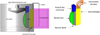 |
Fig. 1 Schematic representation of the core vessel with one cooling sector (left) and description of a sector (right). |
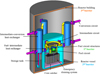 |
Fig. 2 Schematic view of the main systems located in the reactor building; proposals for the confinement barriers are highlighted. |
2.2 MSFR specificities impacting the safety functions
The MSFR has different features from most current reactors. The objective of this paragraph is to explain some of the characterizing aspects of MSFR that are related to the three safety functions: reactivity control, heat removal and confinement.
2.2.1 Reactivity control
Some specificities of the MSFR affect the neutronics. First, the delayed neutron precursors are drifted in low importance areas because of the fuel motion. This implies a reduction of the effective fraction of delayed neutrons from about 310 to 124 pcm [14]. Then, the MSFR has a strong negative global thermal feedback coefficient, around −8 pcm/K [15], coming half from the Doppler feedback effect and half from the density feedback effect. The density effect comes from the fuel expansion and is linked to the presence of free levels in the upper part of the fuel circuit: in case of fuel expansion, a small portion of the fuel salt is thus pushed from the core central area where most of the fissions occur toward the upper part of the fuel circuit where fissions are negligible. Free levels are located at the level of the pumps, at the level of the separation chamber of the gas processing unit and at the level of the expansion vessel (a tank located just above the core in the upper reflector). The intrinsic temperature feedback effects act rapidly since the heat is produced directly in the coolant. This inherently limits power excursion in case of accidental transients.
Thanks to the fuel online cleaning and the processing/loading during reactor operation, the fuel composition is assumed not to encounter large variations. In fact, the amount of fissile material dissolved in the critical zone of the fuel circuit is just necessary to maintain a critical state and fertile material periodically injected in the core without needing to shut down the reactor. Therefore, it should not be necessary to have a large in-core reactivity margin to compensate the fuel depletion.
Thanks to the negative thermal feedback effects, the reactor can be mainly driven by heat extraction [14]. No control rods are currently foreseen in the MSFR design. Nonetheless, the injection of gas bubbles in the core may be used to control the reactivity. Besides, fuel salt draining towards the routine draining tank or toward the EDS can ensure reactivity control.
2.2.2 Heat removal
In normal operation, the systems involved in the heat evacuation are the fuel circuit, the intermediate circuit, the conversion circuit and the heat sink. Additionally, several systems, preferentially relying on passive mechanisms, are foreseen to evacuate the residual power from the fuel with, in particular, the implementation of an emergency cooling system for the intermediate circuit, with air as heat sink. Besides, one of the consequences of the fuel liquid state is the possibility of a passive reconfiguration of the geometry of the core. In case of failure to remove heat from the fuel circuit, the fuel can be drained gravitationally toward the EDS where its subcriticality is ensured. The cooling system of the EDS, also under study in the frame of the SAMOFAR project, aims at allowing a passive removal of the residual heat with no need for forced convection (both in the EDS and in its cooling circuit) [8,12,16].
One of the MSFR specificities is the delocalization of a part of the residual power out of the core, notably because of the in-core gas bubbling and of the fuel processing. On the one hand, the residual power produced in the salt is reduced and, 1s after reactor shutdown, represents only ∼4% of the nominal power. On the other hand, the heat evacuation from the bubbling system (representing ∼1.5% of nominal power 1s after reactor shutdown) and from the processing unit (representing ∼0.06% of nominal power 1s after reactor shut down) should also be handled with [17]. Fission products extracted in reprocessing and stored in special on-site tanks are not further considered in this article.
2.2.3 Confinement of radioactive materials
Preliminary safety studies [17] have led to the definition of the integrated fuel circuit geometry presented above (see Fig. 1) and now used as reference in the SAMOFAR project. In case of heat exchanger leak, fuel dispersion is limited by using a slightly higher operating pressure in the intermediate circuit than in the fuel circuit. In addition, several valves are implemented to be able to ensure the confinement of the radioactive materials at the intermediate circuit level if needed: on the intermediate circuit leg entering the core vessel (this valve could also be used to isolate a sector for maintenance operations), on the intermediate circuit leg crossing the reactor vessel and on the intermediate/conversion circuit leg (depending on the secondary heat exchanger location) crossing the reactor building.
In the frame of the SAMOFAR project, several proposals have been investigated for the definition of the MSFR confinement barriers. In one of these proposals, the confinement barriers with regard to fuel salt in the fuel circuit, in normal operation during power production, are defined as follows [6]:
-
1st barrier: fuel circuit containment structures (represented in green on Fig. 2) that ensure fuel containment during normal operation;
-
2nd barrier: reactor vessel (represented in blue on Fig. 2) that ensures fuel containment when the function can no longer be ensured by the first barrier (e.g., first barrier leakage or fuel salt draining in the EDS);
-
3rd barrier: reactor building (represented in orange on Fig. 2) that ensures protection of the two first barriers with regard to external hazards, and may have a dynamic confinement function (and static confinement function in case of postulated failures of the two first barriers).
The constraints on these confinement barriers are quite different from the ones classically encountered on “solid fuel” reactors. It is worth noting here that the MSFR fuel circuit is at low pressure. Since both fuel and intermediate circuits are at low pressure (the only circuit with a high pressure being the energy conversion circuit) and no highly exothermic chemical reaction has been identified until now, the constraints on the third barrier, the reactor building, may be rather low (potentially no need for a high pressure resistant containment, provided the energy conversion circuits are located out of the reactor building).
The fuel can be located in several areas of the plant: storage tanks, sampling system, processing unit, etc. Thus, the definition of the confinement barriers should be undertaken for each possible location of the fuel and for each state of the reactor operation: power production, maintenance, start up, shut down, normal and accident conditions.
3 Lines of Defence methodology
The main objective of the Lines of Defence (LoD) method is to ensure that every accidental evolution of the reactor state is always prevented by a minimum set of homogenous (in number and quality) safety provisions − called Lines of Defence − before a given situation may arise. It allows the designer to determine whether sufficient safety provisions are put in place between initiating events and a given accidental situation, and contributes to justify the acceptable safety level of the plant in the licensing process. It is a deterministic method particularly well suited to early design phases as it can be used as a pragmatic guidance for the architecture of the safety components and systems, consistently with the Defence in Depth principle. The method is also relevant for the identification and the classification of accidental sequences.
This method has been widely used in the past on French fast reactors, and is being used in the fast reactor project ASTRID [18] and other projects (e.g. Jules Horowitz Reactor in Cadarache), for the prevention of the reactivity control and decay heat removal safety function(s).
3.1 The LoD method generic steps
A very first step of the method is to identify and characterize the situations for which prevention is studied. Then, the events that may lead to the situation considered (so-called initiating events) must be identified.
For a given accidental situation to be prevented (typically, severe accident), the main steps of the LoD method are:
-
1.
define the required number and quality of LoDs to be provided for the prevention of this accidental situation (the analysis is performed for each function necessary to prevent the accident situation);
-
2.
for each initiating event, ensure that an adequate set of LoDs (in terms of number and quality) is provided:
-
at early design stages when the safety architecture is to be built, the method provides a guidance to sketch the safety architecture;
-
when the safety architecture is defined into more details, the method permits to check its sufficiency, and allows the classification of accidental sequences upstream accident analyses.
-
3.2 Lines of Defence definition
There are three types of LoDs: the preventive measures of the initiating event (the low occurrence frequency of the initiating event can by itself stand for a line of defence); the measures aimed at limiting the consequences of the initiating event by means of specific equipment or human actions; and the intrinsic behaviour and natural resistance to the progression of the initiating event.
The lines of defence are classified according to their expected availability/reliability:
-
Strong LoD, type “a” (initiating event with a frequency lower than 10−3 to 10−4/year, equipment with a failure rate of approximately 10−3 to 10−4 when needed);
-
Medium LoD, type “b” (initiating event with a frequency lower than 10−1 to 10−2/year, equipment or operator's procedure with a failure rate of approximately 10−1 to 10−2 when needed).
The experience feedback [18] is that the following provisions can be considered as LoD:
-
Strong LoD (type “a”) can include active systems designed in accordance with the standards of the nuclear industry and comprising internal redundancies as well as electrical back-up; passive equipment, exploited like confinement barriers, designed in accordance with the standards of the nuclear industry; intrinsic behaviour providing a long grace period to perform human corrective actions. The systems used as strong LoD must be designed to withstand hazards (notably earthquake).
-
Medium LoD (type “b”) can include active systems without internal redundancy; actions by the operator in the frame of procedures.
Two medium independant lines of defence may be considered as equivalent to one strong line of defence.
One of the essential points in the application of this method is to make sure that the LoDs implemented for a specific initiating event are independent from the initiating event and from each other in order to minimize the risks of common mode failure, by ensuring sufficient diversification and functional and physical independence between them [18].
3.3 LoD general application in the MSFR context
3.3.1 Severe accident definition in the MSFR context
The definition of the severe accident is key in the usual application of the LoD method.
For example, on the ASTRID project, a complete core meltdown is considered as severe accident. Then, for each initiating event, the equivalent of three LoDs is implemented (at least two strong lines and one medium line, “2 · a + b”) upstream from this assumed situation of severe accident [18].
Cliff edge effects studies, allowing to precisely define severe accident for the MSFR, are still on-going. For the MSFR, considering the barriers envisaged (see Sect. 2.2.3), a situation with potential for large early radiological releases in the environment would require at least the failure of the two first barriers.
The general objective retained is thus to prevent the situation of failure of the two first barriers, with a potential for large early radiological releases in the environment, through at least two strong and one medium lines of defence (2 · a + b). The related mitigation means of such situation are not further developed in the present article.
As regard to situations that may need to be practically eliminated (i.e., severe accident situations that may lead to large early releases and that would not be reasonably manageable), none has been identitied until now.
3.3.2 Required LoDs after MSFR initiating events
Consistenly, the purpose of investigating the challenges of the first barrier has driven the process of identification of the initiating events. (In case of failure of the first barrier, safety provisions to ensure leaktightness of the second barrier are then to be studied).
The initiating events challenge the reactor and its safety functions; they are grouped in families depending on their potential effects on the reactor [5]. For each family, specific initiating events to be further analysed have been selected. In this paper, the application of the LoD method to some of them is presented. An initiating event initiates the accidental sequence. The accidental sequence is the evolution of the accident from the initiating event until the final consequences and damage. The consequence is the effect in physical terms of a particular accident and the damage represents the last impact of failures/accidents on the population, the environment, structures/assets, and reputation (in this work it is quantified in terms of loss of availability of the system, loss of investment, or potential for radiological releases). The prevention and mitigation of the accidental sequence is given by the implementation of LoDs.
The list of MSFR initiating events has been divided into three categories with incidents, accidents and limiting events [5]. Limiting events are very rare events postulated in complement to accidents, to ensure the avoidance of cliff edge effects in terms of radiological releases.
Since the occurrence frequency of an initiating event can stand for a LoD by itself, it is considered in the LoD method application to MSFR that:
-
the occurrence frequency of an incident may be considered as an initial medium LoD (b) if it is lower than 10−1 to 10−2/year (if not, no LoD should be accounted for the occurrence of the incident);
-
the occurrence frequency of an accident may be considered as a strong LoD (a) if it is lower than 10−3 to 10−4/year (if not it should be considered at least as a medium LoD);
-
the occurrence frequency of a limiting event is equivalent to two strong LoDs (2 · a).
With regard to a given situation, the number of LoD required to cope with an initiating event depends on the LoD associated to the occurrence of the initiating event. In practice, as regard the situation with failure of the two first barriers with a potential for large early radiological releases in the environment (hereafter called the “feared situation”), two strong and one medium lines of defence (2 · a + b) are required. Therefore, this means that:
-
after incident or accident whose occurrence can be counted as a medium LoD (b), two strong LoDs (2 · a) are required to cope with the event before occurrence of the feared situation;
-
after accident whose occurrence can be counted as a strong LoD (a), one strong LoD and one medium LoD (a + b) are required to cope with the event before occurrence of the feared situation;
-
after limiting event whose occurrence can be counted as two strong LoDs (2 · a), one medium LoD (b) is required to cope with the event before occurrence of the feared situation.
In the end, this should ensure that a set of two strong and one medium LoDs (2 · a + b) is always available between normal operation and occurrence of the feared situation.
Additionally, concerns related to the prevention of radiological releases (not only the prevention of large early releases), as well as availability and investment protection concerns, are introduced in the LoD application for MSFR, as part of a graded approach.
3.4 LoD application process for the study of each initiating event on MSFR
Among the list of initiating events established with regard to the risk of fuel circuit (primary barrier) leak, the LoD application presented hereafter is led with regard to the following initating events:
-
a loss of main heat sink event;
-
an overcooling event.
In a more detailed manner, the following steps are followed for the LoD application:
-
For each initiating event studied, a description of this event is provided along with an evaluation of its occurrence frequency, to determine whether or not the occurrence frequency of the event can be counted as LoD.
The potential consequences of the initiating event considered, in the absence of any safety limitation feature (natural behaviour), are preliminarily assessed on the basis of previous studies, and considering on-going calculations in the SAMOFAR project, in particular as regard to the risk of failure of the first confinement barrier, then the failure of the second confinement barrier.
The goal of this evaluation is finally to define the number and quality of the LoDs required to cope with the initiating events, in function of its potential consequences.
-
With regard to sequences or situations which could threaten safety, with a potential for large early radiological releases, prevention by at least two strong and one medium LoDs (2 · a + b)1 is required. In practice, the corresponding situation in the MSFR design is here defined as the loss of the two first barriers with release of a large source term in the third barrier.
-
With regard to sequences or situations which could significantly impair investment protection or lead to radiological releases (but with no need for off-site confinement measures), at least one strong LoD (a)1 is studied.
-
With regard to sequences or situations which could significantly impair the reactor availability or lead to limited radiological releases (but significantly exceeding normal operation releases) at least one medium LoD (b)1 is studied.
For the last two categories, the corresponding situations are defined more precisely when analysing each initiating event and its potential consequences.
-
-
Then, considering the MSFR current architecture, a first identification of the possible lines of defence in the current MSFR architecture is performed. This set of lines of defence is compared to the required number of lines of defence previously defined. To do so, event trees are used to determine the different sequences possible according to the success or failure of the possible lines of defence in the current MSFR architecture. For each sequence, a comparison is made between the corresponding number of failed LoDs, and the required number of LoDs. This allows to provide a first feedback on the MSFR design and to point out possible improvements in the safety architecture.
-
Preliminary outcomes of this LoD application are summarized in the end.
4 Results
The LoD method is being applied to a selection of relevant initiating events of the MSFR. In this section, the method is illustrated on two examples: a loss of main heat sink (LOHS) event, and an overcooling (OVC) event. For each example, the following elements are described: the initiating event considered (IE), the potential consequences (evolution of the accident in unprotected conditions considering only the natural behavior of the plant) and the corresponding required number of prevention LoDs, the possible LoDs to cope with the event in the current MSFR design, and finally some preliminary outcomes of the method application when comparing required LoDs and possibly available LoDs in the current design.
4.1 Loss of main heat sink event
4.1.1 Description of the initiating event
The loss of the main heat sink could result from a failure of the energy conversion circuit or a failure to remove the heat from this circuit. This event is classified as an incident in the classification of the MSFR initiating events performed in the frame of the SAMOFAR project [16,19,6]. The loss of main heat sink event is assumed to be frequent, as it may be caused by equipment from the tertiary circuit or support equipement (such as the electrical grid). Therefore, the frequency of this event is not considered as a LoD.
4.1.2 Potential consequences and required number of LoDs
The loss of main heat sink implies that the heat removal from the intermediate salt circuit is no longer ensured. Conservatively, it is assumed for the study of this event that the heat transfer from the intermediate salt circuit to the conversion circuit immediately stops at the beginning of the event. As the heat removal from the intermediate salt circuit stops, the heat removal from the fuel salt circuit decreases. The fuel temperature increase causes the decrease of the chain reaction and of the neutronic power down to a negligible low level. The fuel salt temperature further continues to rise due to the residual power. As the fuel salt circulation still operates (if the pumps are still electrically supplied), the temperatures in the fuel circuit tend to homogenize. The intermediate loops act as a thermal buffer, which helps to attenuate the temperature rise. Taking this into account, the fuel mean temperature exceeds 1100 °C after more than one hour and a half [16,19]. The structures, made of Hastelloy N, may thus undergo high temperatures so that their leak tightness can be challenged with a loss of investment and potential safety consequences in terms of releases. Indeed, a leak in the bottom part of the fuel circuit may occur, but also in other parts of the fuel circuits: for instance, at the interface with the fertile blanket, at the intermediate heat exchanger level, etc. Concerns associated to fuel salt heating are also related to the confinement of the radioactive materials as the temperature increase enhances the risk of release and dispersion of the fission products contained in the fuel salt.
At the intermediate circuit level, the intermediate salt temperature increases and homogenizes. If the fluoroborate is selected as the intermediate salt, the salt decomposition should occur with the formation of BF3, thus leading to pressurization of the circuit [16]. As the structural material of the intermediate circuit may not withstand the high temperature achieved, it is possible that the intermediate circuit fails. A leak at the fuel-intermediate heat exchanger is also a concern to be further studied, given the risk of siphoning of the fuel salt towards the intermediate circuit.
A scenario with complete and long-term loss of the fuel salt decay heat removal function has not been studied in details up to now. At this stage, it is assumed that failure to ensure the decay heat removal function can lead to failure of the barriers containing the fuel salt (first at the fuel circuit level, and further at the reactor vessel level if cooling is not ensured at this level either) with a large source term involved.
– Therefore two strong and one medium LoDs (2 · a + b) are required for coping with the loss of main heat sink event, before occurrence of a situation with failure to ensure decay heat removal from the fuel salt.
The LoDs put in place must ensure a sufficient fuel salt cooling so that the confinement function can still be ensured at the first or second barrier level.
The analysis presented hereafter is firstly focused on the decay heat removal issues.
4.1.3 Possible lines of defence in the current MSFR architecture
4.1.3.1 With regard to the decay heat removal function
The foreseen LoDs for the loss of heat sink scenario are presented through the schematic event tree, in Figure 3. When the main heat sink fails, the emergency cooling system for the intermediate circuit must be actuated to cool down the fuel salt in the fuel circuit. This system may be counted as a strong LoD, considering that several independent redundant circuits are provided on the different intermediate loops (with a natural convection mode aimed at). In case of its failure, in order to limit the temperature rise in the fuel salt circuit, an automatic draining through redundant valves opening in the lower region of the fuel circuit is foreseen and accounted for as a strong LoD. In case of failure of the automated valves, fusible plugs can provide a passive draining and are counted as a strong LoD. The drained fuel salt is sent in the emergency draining system (EDS), where the fuel salt is cooled by a dedicated cooling system. The emergency draining tank is considered as a strong LoD. It can be noted that, in case of failures of all the valves, a leak of the fuel salt circuit could still be recovered by the EDS since it is positioned below the fuel circuit. Last, in case of fuel salt relocation in the EDS and subsequent failure of the EDS, either due to EDS leakage or failure of its dedicated cooling system, further relocation of the fuel salt in the bottom part of the reactor vessel may be considered. A “core catcher”, along with its cooling system, is envisaged in the MSFR design, standing for a strong LoD.
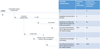 |
Fig. 3 Schematic event tree of the loss of main heat sink event (decay heat removal function). |
4.1.3.2 With regard to the reactivity control function
In the evaluation process, it must also be checked that reactivity control is properly ensured. At the fuel circuit level, reactivity control can be ensured by the negative thermal feedback effects (considered as a strong LoD, at least). Should it not be the case, this could result in a fuel temperature increase and thus lead to fuel draining in the EDS. In the EDS, the fuel sub-criticality is ensured by the geometry of the EDS (considered as a strong LoD, at least). At the core catcher level, sub-criticality should be ensured through fuel salt spreading and mixing with a diluant salt (considered as a strong LoD). The reactivity control provisions thus are consistent with the ones envisaged for decay heat removal.
4.1.4 Preliminary outcomes
With the LoDs identified until now and schematically represented in the above event tree presented (see Fig. 3), 3 · a LoDs are identified before failure of the two first barriers with a significant radiological source term in the last barrier (therefore a potential for large early releases) can occur in case of loss of heat sink. The prevention of this situation requires 2 · a + b according to the LoD method.
The independency of the LoDs being a major hypothesis of the method, the absence of credible common cause failures between the intermediate salt gas cooling system, the EDS cooling system and the core catcher cooling system should be guaranteed and verified during further design stages.
More generally, the allocation of LoDs may be different (but in the end, the required number of LoD stays as 2 · a + b). Other design arrangements may thus be studied.
In this study, it has been considered that any fuel salt leak from the fuel circuit is recovered in the EDS. In the course of the accidental sequences, the risk of an intermediate heat exchanger leak should also influence the scenario and should be further studied.
The study has been focused on the loss of main heat sink with the fuel salt in the core vessel. Events likely to challenge the fuel salt cooling when the fuel salt is in the routine draining tanks during reactor shutdown states, should also be considered and analyzed according to the LoD method, in order to define a comprehensive set of safety provisions as regard to fuel salt cooling.
4.2 Overcooling at low power
4.2.1 Description of the initiating event
In the present study of an overcooling (OVC) at low power event, it is postulated that both the fuel salt and intermediate salt are at the nominal mean fuel temperature of 725 °C, and that the heat extraction at the conversion circuit level suddenly increases from a few kW up to nominal power (theoretical case at this stage).
The overcooling from low power is considered for the analysis compared to the overcooling from nominal power as there is a higher potential for overcooling from low power state. The start-up procedure is not completely defined; nevertheless, it will foresee a progressive reactor power increase [20]. It is assumed at this stage that the frequency of the event can be counted as one medium LoD, since it would imply non respect of the progressive start-up procedure. This event is classified as an accident in the classification of the MSFR initiating events performed in the frame of the SAMOFAR project [16,19,6].
4.2.2 Potential consequences and required number of LoDs
At the beginning of such transient, the temperature in the cold leg of the intermediate circuit is rapidly lowered. It causes a cooling down of the fuel salt, with a positive reactivity insertion and an increase of the reactor power. If the intermediate cold leg temperature is lowered too fast, it is theoretically possible to encounter a prompt critical jump. Indeed, preliminary safety studies have shown that, if the extracted power reaches the nominal power in less than 30 seconds, prompt criticality can be reached [14]. The fuel temperature increases but considering the fast reactivity feedbacks, the prompt critical jump is very short and the temperature elevation remains limited in the calculations performed up to now, below 800 °C [14]. The prompt critical jump may also result in a pressure wave. Should fuel salt expansion not be possible, this could result in a sustained prompt critical jump with sudden and significant energy release and pressure increase.
A situation with prompt critical power excursion has not been studied in details up to now. A sustained prompt critical jump may damage the first two barriers and the third one additionally, with a potential for large early releases in the environment.
Therefore, conservatively at this stage2, at least two strong and one medium LoDs (2 · a + b) are required for coping with the overcooling at low power event, before occurrence of a situation with prompt critical power excursion.
The analysis presented hereafter is firstly focused on the reactivity control issues, as the potential consequences previsously identified mainly relate to reactivity issues.
4.2.3 Possible lines of defence in the current MSFR architecture
4.2.3.1 With regard to the reactivity control function
The foreseen LoDs for the overcooling scenario are presented through the schematic event tree in Figure 4. First, detection measures could be studied before reaching a large reactivity insertion, based, for example, on the temperature decrease in the cold leg of the fuel circuit or of the intermediate circuit, or on the power variation. The corrective measures could consist of a stop of the energy conversion system or valves closure on the intermediate circuit. The efficiency of such measures should be checked, with a special attention to the time constants and the possibility to detect the event early enough. At this stage, these measures are considered equivalent to a medium LoD.
Then, even if no corrective measures are taken, the consequences of the event are limited thanks to the fast action of the neutronic feedback reactions coming from the Doppler and the density effects. This last effect supposes that the fuel salt expansion is possible and requires the presence and availability of the free levels, expansion volumes in the upper part of the fuel circuit. In particular, the fuel salt system has three kinds of free surfaces that can help to manage temperature increases and the consequent liquid fuel volume dilation:
-
the central opening for the fuel periodical transfers, located in the upper reflector;
-
the salt-gas separators with controlled pressurization, located above the fuel salt sectors, supposedly at low pressure for efficient degassing;
-
the routine draining siphons (see Fig. 2), which are attached to the vessel, not to the sectors, and have their own pressurization. The inert gas is returned to the vessel during draining via the sampling opening in the expansion tank.
It is difficult to allocate a priori a weight in terms of LoD to this quite intrinsic design feature. The LoD method allows to identify a posteriori how many LoDs are still required and thus provide an indication on the reliability level that could be expected from this design feature.
 |
Fig. 4 Schematic event tree of the overcooling event (reactivity control function). |
4.2.3.2 With regard to the decay heat removal function
In the course of the accident management, attention should further be paid to decay heat removal concerns. It should notably be checked that the LoDs envisaged for reactivity control are not likely to lower the Decay Heat Removal (DHR) systems expected reliability.
The current design must be such that the loss of DHR capabilities by the intermediate salt gas cooling system is equivalent to one strong line of defence (cf. Sect. 4.1). In particular, valves closure of the intermediate salt circuits upon detection of the above overcooling event has been identified as a possible LoD for reactivity control: the design should be adapted so that DHR by the intermediate salt gas cooling system remains available in such case (avoid to make unavailable a DHR system that stands for a strong LoD after the occurrence of an initiating event that stands for a medium LoD), or other corrective measures should be favored (such as stop of the energy conversion system).
4.2.4 Preliminary outcomes
It should be studied that the design of the reactor, and of the energy conversion system in particular, and start-up procedure are such that the worst overcooling scenario possible remains sufficiently progressive with a time constant for the temperature decrease of the intermediate salt cold leg above 30 seconds.
Concerning the rapid overcooling scenario, there is an interest to look for detection and corrective measures allowing limitation of the reactivity insertion.
With the LoDs identified until now and according to the schematic event tree presented in Figure 4, at least a + b LoDs should be available, in complement to the start-up procedure and first detection and correction measures, before occurrence of a prompt critical jump. In this frame, a focus should be made to ensure the availability of fuel thermal expansion effect (considering notably the possibility to introduce diversity and monitoring). Another possibility would be to increase the reliability of the detection and correction measures (making it a strong LoD so that only one strong LoD is required in complement for prevention of prompt critical jump).
The availability of the free levels to allow the fuel salt expansion thus appears absolutely necessary. This point deserves to be studied more deeply. Indeed, some events could limit the capacity or the availability of the free levels: excessive initial fuel salt pouring, blockages, etc. A detailed analysis of all scenarios that might lead to free level unavailability would be worthwhile, in order to ensure that appropriate design measures ensure a very high reliability of fuel thermal expansion through those free levels.
5 Conclusions
The application of the LoD has been adapted and employed for the specific case of the MSFR, whose one of the main characteristics is the liquid state of the fuel. A prevention objective of two strong and one medium lines of defence (2 · a + b) has been defined before occurrence of a situation with failure of the two first barriers, with a large radiological source term in the last barrier (hence a potential for further large early releases in the environment).
The application of the LoDs method has been useful to highlight the need for further evaluations and to provide some first feedbacks on the design; in particular:
With regard to the loss of main heat sink event
-
Two strong and one medium lines of defence (2 · a + b) are required before occurrence of a situation with complete loss of the fuel salt heat removal function. This notably points out the need to further study the situation where the fuel salt is drained in the EDS, with subsequent EDS failure: in this case, the fuel salt would go in the core catcher and appropriate cooling means must be defined.
-
The DHR systems (intermediate gas cooling system, EDS and its cooling system, and core catcher and its cooling system) should be designed in order to prevent the risk of common cause failure. Other DHR architectures may also be envisaged, provided the whole requirement in terms of LoDs required is still respected.
With regard to overcooling at low power event
-
At least one strong and one medium LoDs (a + b) should be available, in complement to the start-up procedure and first detection and correction measures, before occurrence of a prompt critical jump.
-
The availability of the fuel salt expansion effect appears as absolutely necessary: a detailed analysis of all scenarios that might lead to fuel circuits' free levels unavailability would be worthwhile, in order to ensure that appropriate design measures ensure a very high reliability of this safety feature.
-
The reactor behavior in case of prompt critical jump should be studied in more details.
Acknowledgments
This project has received funding from the Euratom research and training programme 2014–2018 under grant agreement No 661891. The authors also wish to thank the NEEDS (Nucléaire: Energie, Environnement, Déchets, Société) French program, the IN2P3 department of the National Centre for Scientific Research (CNRS) and Grenoble Institute of Technology for their support. The content of this article does not reflect the official opinion of the European Union. Responsibility for the information and/or views expressed therein lies entirely with the author(s).
References
- H. Boussier et al., The Molten Salt Reactor in Generation IV: Overview and Perspectives, in Proceedings of the Generation4 International Forum Symposium, San Diego, USA , 2012 [Google Scholar]
- J. Serp, M. Allibert, O. Beneš, S. Delpech, O. Feynberg, V. Ghetta, D. Heuer, D. Holcomb, V. Ignatiev, J.L. Kloosterman, L. Luzzi, E. Merle-Lucotte, J. Uhlíř, R. Yoshioka, D. Zhimin, The molten salt reactor (MSR) in generation IV: Overview and Perspectives, Prog. Nucl. Energy 77 , 308 (2014) [Google Scholar]
- SAMOFAR Strategic Advisory Board, A paradigm Shift in Nuclear Reactor Safety with the Molten Salt Fast Reactor (SAMOFAR kick-off meeting), 2015 [Google Scholar]
- A. Carpignano, S. Dulla, Y. Flauw, D. Gérardin, D. Heuer, D. Lecarpentier, E. Merle, E. Ivanov, V. Tiberi, A. Uggenti, Development on an integral safety assessment methodology for MSFRs. SAMOFAR (A Paradigm Shift in Nuclear Reactor Safety with the Molten Salt Fast Reactor), European project, Work-Package WP1, Deliverable D1.5, Grant Agreement number : 661891, 2018 [Google Scholar]
- D. Gérardin, A. Uggenti, S. Beils, A. Carpignano, S. Dulla, E. Merle, D. Heuer, A. Laureau, M. Allibert, A methodology for the identification of the postulated initiating events of the Molten Salt fast reactor, Nucl. Eng. Technol., in press [Google Scholar]
- A. Uggenti, D. Gérardin, A. Carpignano, S. Dulla, E. Merle, D. Heuer, A. Laureau, M. Allibert, Preliminary functional safety assessment for molten salt fast reactors in the framework of the SAMOFAR project, in Proceedings of the International Topical Meeting on Probabilistic Safety Assessment and Analysis (PSA 2017), Pittsburgh, USA , 2017 [Google Scholar]
- A. Uggenti, D. Gérardin, S. Beils, A. Carpignano, S. Dulla, D. Heuer, A. Laureau, J. Martinet, E. Merle, Identification of risks and phenomena involved, identification of accident initiators and accident scenarios. SAMOFAR (A Paradigm Shift in Nuclear Reactor Safety with the Molten Salt Fast Reactor), European project, Work-Package WP1, Deliverable D1.6, Grant Agreement number : 661891, 2018 [Google Scholar]
- M. Allibert, D. Gérardin, D. Heuer, E. Huffer, A. Laureau, E. Merle, S. Beils, A. Cammi, B. Carluec, S. Delpech, A. Gerber, E. Girardi, J. Krepel, D. Lathouwers, D. Lecarpentier, S. Lorenzi, L. Luzzi, S. Poumerouly, M. Ricotti, M. Tiberga, V. Tiberi, Description of initial reference design and identification of safety aspects. SAMOFAR (A Paradigm Shift in Nuclear Reactor Safety with the Molten Salt Fast Reactor), European project, Work-Package WP1, Deliverable D1.1, Grant Agreement number: 661891, 2015 [Google Scholar]
- O. Beneš, R.J.M. Konings, Thermodynamic properties and phase diagrams of fluoride salts for nuclear applications, J. Fluorine Chem. 130 , 22 (2009) [CrossRef] [Google Scholar]
- O. Beneš, M. Salanne, M. Levesque, R.J.M. Konings, Physico-chemical properties of the MSFR fuel salt. EVOL (Evaluation and Viability of Liquid fuel fast reactor system) European FP7 project, Work-Package WP3, Deliverable D3.2, Contract number: 249696, 2013 [Google Scholar]
- Haynes international, HASTELLOY R N alloy, Marketing brochure, 2017 [Google Scholar]
- D. Gérardin, M. Allibert, D. Heuer, A. Laureau, E. Merle-Lucotte, C. Seuvre, Design Evolutions of the Molten Salt Fast Reactor, in Proceeding of International Conference on Fast Reactors and Related Fuel Cycles: Next Generation Nuclear Systems for Sustainable Development (FR17), Yekaterinburg, Russia , 2017 [Google Scholar]
- M.W. Rosenthal, P.R. Kasten, R.B. Briggs, Molten-salt reactors-history, status, and potential, Nucl. Appl. Technol. 8 , 107 (1970) [CrossRef] [Google Scholar]
- A. Laureau, D. Heuer, E. Merle-Lucotte, P. Rubiolo, M. Allibert, M. Aufiero, Transient coupled calculations of the Molten Salt Fast Reactor using the Transient Fission Matrix approach, Nucl. Eng. Des. 316 , 112 (2017) [CrossRef] [Google Scholar]
- A. Laureau, Développement de modèles neutroniques pour le couplage thermohydraulique du MSFR et le calcul de paramètres cinétiques effectifs, PhD Thesis, Grenoble-Alpes University, 2015 [Google Scholar]
- D. Gérardin, Développements de méthodes et outils numériques pour l'étude de la sûreté du réacteur à sels fondus MSFR, PhD Thesis, Grenoble Institute of Technology, France, 2019 [Google Scholar]
- M. Brovchenko, Etudes préliminaires de sûreté du réacteur à sels fondus MSFR, PhD Thesis, Grenoble Institute of Technology, France, 2013 [Google Scholar]
- P. Lo Pinto, L. Costes, B. Carluec, P. Quellien, S. Beils, L. Bourgue, ASTRID Safety Design: Progress on Prevention of Severe Accident, in International Conference on Fast Reactors and Related Fuel Cycles: Next Generation Nuclear Systems for Sustainable Development (FR17), Yekaterinburg, Russia , 2017 [Google Scholar]
- D. Gérardin, M. Allibert, D. Heuer, A. Laureau, J. Martinet, E. Merle, Identification and Study of Incidental an Accidental Scenarios for the Molten Salt Fast Reactor, in Proceedings of Fourth International Conference on Physics and Technology of Reactors and Applications (PHYTRA4), Marrakech, Maroc , 2018 [Google Scholar]
- D. Heuer, A. Laureau, E. Merle-Lucotte, M. Allibert, D. Gerardin, A starting procedure for the MSFR: approach to criticality and incident analysis, in Proceedings of the ICAPP'2017 International Conference, Kyoto, Japan , 2017 [Google Scholar]
Including the LoD that can be represented by the occurrence frequency of the initiating event.
In the sense that, should a situation of prompt critical jump be demonstrated acceptable with a high level of confidence, the prevention level required might be alleviated.
Cite this article as: Stéphane Beils, Delphine Gérardin, Anna Chiara Uggenti, Andrea Carpignano, Sandra Dulla, Elsa Merle, Daniel Heuer, Michel Allibert, Application of the lines of defence method to the molten salt fast reactor in the framework of the SAMOFAR project, EPJ Nuclear Sci. Technol. 5, 18 (2019)
All Tables
All Figures
|
Fig. 1 Schematic representation of the core vessel with one cooling sector (left) and description of a sector (right). |
| In the text | |
|
Fig. 2 Schematic view of the main systems located in the reactor building; proposals for the confinement barriers are highlighted. |
| In the text | |
|
Fig. 3 Schematic event tree of the loss of main heat sink event (decay heat removal function). |
| In the text | |
|
Fig. 4 Schematic event tree of the overcooling event (reactivity control function). |
| In the text | |
Current usage metrics show cumulative count of Article Views (full-text article views including HTML views, PDF and ePub downloads, according to the available data) and Abstracts Views on Vision4Press platform.
Data correspond to usage on the plateform after 2015. The current usage metrics is available 48-96 hours after online publication and is updated daily on week days.
Initial download of the metrics may take a while.